Related Articles


Well Data Requirements for Cement Job Design
For a cement job to be successful, the engineer must determine these important parameters:
- Volume of cement required
- Setting time required
- Ensuring that the cement will get into position
- Ensuring that the cement will not damage the formation
To answer these questions, three categories of information are needed:
- Well depth and hole/casing dimensional data
- Wellbore environment: pressure regime, fluid chemistry, rock mechanics
- Wellbore temperature regime
These data will determine the cement properties required and the additives to be used to achieve them, the slurry and spacer volumes to be pumped, and the flow regimes.
Well Depth and Dimensional Data
The data required include:
- Vertical depth
- Measured depth
- Angles and azimuths of deviation
- Type of casing string (such as full string or liner)
- Casing string size and weight
- Open hole size variation over the length of the drilled section
Depth and deviation are important because no well is exactly vertical and the key to proper centralization of a casing string is knowledge of where deviations in the wellbore will cause the casing to lie against the wellbore wall and require centralizers.
In principle, the wellbore size is determined by the drill bit diameter; but in fact a wellbore is rarely cylindrical. The variation in hole shape will affect the cement volume calculations, the displacement mechanics and the need for centralizers. Openhole caliper logging devices are run into the hole prior to running the casing string to get an accurate picture of the hole size variation with depth (Figure 1).

The greater number of arms on the caliper tool, the better the accuracy of the interpretation. Calipers are typically run with various logging tools, but a minimum of four arms are needed for a good measurement. Hole size can also be measured ultrasonically with a rotating sensor.
Caliper logs are not typically run in the large diameter surface hole sections of a well bore, where the calculation of cement volume is typically boosted by the addition of a excess amount of cement to ensure adequate annular coverage. The amount of excess required is based on local experience.
With the increased use of logging-while-drilling (LWD) or measurement-while-drilling (MED) tools, the size of the open hole can be determined from acoustic measurements and transmitted in real time during drilling and pipe tripping operations. Specialized software can be used to display this information or convert it into required fluid volumes.
Knowing specific wellbore characteristics – for example, the presence and location of pay zones, water aquifers, salt sections, fractured zones, and shale intervals that can expand into the wellbore – is critical in cement job planning. Most important are the expected formation pore pressures and formation fracture pressures along the wellbore. Pore pressure data will have been developed in the well planning phase of the project, or collected during drilling and logging operations. Where MWD has been used, this information may be quite detailed along the well path.
The fracture pressure gradient (Figure 2) is important to understanding the limit beyond which cement hydrostatic head will fracture any given formation within the borehole, causing the cement to be lost. This information will have been developed for the drilling process, but may need to be revised based on indications of lost circulation during drilling.
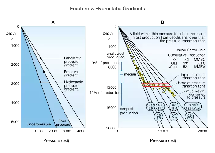
Similarly, understanding the formation pore pressure profile, including sections of the hole that may be underpressured or overpressured is important to predicting where cement slurry properties will be critical to maintaining good hole conditions or avoiding high filtrate loss.
Temperature Regime
When designing a cement job, the bottomhole circulating temperature (BHCT) and the bottomhole static temperature (BHST) must be considered in addition to the temperature difference between the bottom and top of the cement column.
The BHST is the temperature of the undisturbed formation at the final depth in a well. This temperature is measured under static conditions after sufficient time has elapsed to negate any effects from circulating fluids. Tables, charts and computer routines can be used to predict BHST as a function of depth and geographic area, or a temperature log can be run. Log temperatures measured 24 hours after mud circulation may be considered static. The BHST is important for predicting the rate of compressive strength development.
The BHCT is the temperature that the cement slurry will encounter as it is placed in the well and the temperature that must be used for slurry thickening time tests. This temperature will determine what types of retarders or other additives are needed. It is lower than the BHST due to the cooling effect of mud displacement.
The BHCT can be calculated using temperature schedules published in ISO 10426-1-2001 and API 10A. However these standards are only good for typical well conditions and not for deepwater wells or unusually hot wells. Computer simulators that model the physics of heat transfer under dynamic pumping conditions are widely used. These programs consider all of the well parameters affecting BHCT including well geometry, fluid rheology, pump rate, pumping time, and surface injection temperature and are validated using measured downhole temperatures. Using these tools an engineer can predict slurry temperatures at various points in a well over the pumping and displacement time period.
For example, Figure 3 shows the modeled temperature profile as a function of depth in the casing and annulus for a long horizontal well (vertical depth 6,900 ft and measured depth 27,900 ft after one complete cycle of mud circulation immediately before cement placement (510 minutes). The temperature at the bottom of the hole is 167 °F.

The temperature history plot (right) shows the BHCT over time, including the 72 °C (162 ºF) measurement at 510 minutes. The annular and inside casing (tubular) BHCTs are identical, as would be expected. The BHST, also shown in the geothermal profile curve in the plot on the left, is 85 °C (185 ºF). However, the BHCT predicted by the API/ISO schedule is only 53 °C (127 °F), significantly lower than the modeled number. If a retarder had been chosen based on this prediction rather than the more accurate modeled number, the actual thickening time in the well could have been much shorter due to the higher temperature, with potentially serious results.
The temperature difference between the top and bottom of the cement column is also important. For example, cement slurry that has been retarded to ensure adequate time for placement at a given BHCT may remain liquid when circulated back up the annulus to a shallow depth in the well. If adequate compressive strength cannot be obtained at the top of cement (TOC) location, it may be necessary to execute the job in stages.
