Preparing the Geosteering Plan

Know the Target Reservoir
No Geosteering Team can steer a horizontal, or high-angle extended-reach wellbore without first preparing a geosteering plan from surface to kick-off point, and then through to the end of the lateral section. The first critical step in developing the plan is to understand the geology well enough to develop a wellbore path that will exploit the strengths of the reservoir.
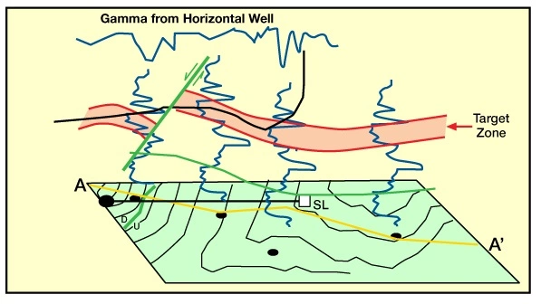
The most important aspect of planning for a Geosteering project is the evaluation of the reservoir itself (Figure 1: Knowing the reservoir – analysis of seismic data plays a key role in planning a horizontal well ).

In order to gain a full understanding of the reservoir, the following must be evaluated prior to drawing up plans for the well.
- Seismic Data and Subsurface Maps: reveal structural style, regional dip, fault frequency and throw, and thickness of the reservoir.
- Core and Log Analysis: provide detailed petrophysical information about the reservoir.
- Geologic Models: identifies sweet spots, porosity distribution, and morphology within the reservoir.
Reservoir Evaluation
To hit and stay in a target, the Geosteering Team must know the characteristic geology of that target and its surrounding stratigraphy. When the target is not where it was anticipated, it will be easier to re-locate if the Geologist knows what the reservoir looks like.
Structure
It is important to use all tools available in evaluating the structure through which the horizontal well will be drilled. Subsurface evaluation should be tied closely to seismic models, when available. Currently, 3-D seismic offers reservoir very good imaging that can be used in developing a wellbore plan. Using 3D seismic, an arbitrary line can be generated to create a seismic profile along the proposed wellbore path. However, velocity variations and inadequate depth conversion can make a large difference in perceived formation dips, so depth conversion must be performed with care. It is also important to remember that the Geosteering Tem needs to know the apparent dip (the dip that the bit will encounter along the wellbore path) rather than true dip.
The structural interpretation should reveal the average dip, the expected magnitude of the maximum and minimum dip, identifiable faults that may affect the wellbore profile, and the structural style. The structural style plays a major role in how a wellbore is steered. For instance, a well that is drilled across an anticline (Figure 2: may take advantage of the structure by drilling a true horizontal well at 90 degrees inclination. In this model, wellbore A or B will traverse down through the target and, as the wellbore crosses the crest, will traverse back up the section with only minor changes in trajectory. A well drilled in this manner may be less expensive than trying to follow a thin bed up-structure, and then turning back down across the crest, as shown in wellbore C).

Average formation dip is important, but even more important is the variation of the dip. Average dip can just be considered a statistical anomaly. The formation very rarely conforms to average dip for any significant distance, but can vary widely across most field structures.
Another important factor is the presence of faults or fractures in the reservoir. In many reservoirs, it is the large faults that extend well below the target horizon which often form the water encroachment zones, while small faults and fractures define the reservoir. In such cases, it is important to identify larger faults to avoid by drilling away, toward the non-faulted areas. In the case when a well encounters an unexpected water-conducting fault, it is generally better to stop drilling immediately rather than to drill past. It is usually easier to squeeze off the end of a hole rather than isolate a zone somewhere in the middle of the lateral.
As with any drilling prospect, the direction and vertical throw of faults are important, and must be accurately determined. When identifying faults on seismic, always remember that if faults can be seen on the seismic line, then you should expect the bit to encounter other faults that are below the resolution of the data. Furthermore, it is very probable that if seismic fails to reveal any faulting at all, there will nonetheless be a few small-scale faults in the well.
Small faults with throws of only 1 to 4 meters will very seldom be visible on a seismic section, yet can make a significant impact in the drilling of horizontal wells. The vertical resolution of the seismic and the depth to target will determine how accurately fault throws can be determined by seismic.
To defer to experience gained by Horizontal Solutions International, in their evaluation of 2000 lateral wells, the actual geology encountered by horizontal wells is always more complex than anticipated, and just a mere 1% of those wells encountered no faulting. Horizontal wells in every formation tend to exhibit at least a few sub-seismic faults. Similarly, vertical logs often do not have sufficient resolution to see faults below 10 feet of displacement, and even if a missing section is seen in a vertical well, it is often attributed to stratigraphic change -especially when the two correlated wells are thousands of feet apart. However, by using appropriate correlations on a horizontal log, very small faults with vertical throws as small as 1 foot have been identified.
An interesting point that has been observed in the evaluation of horizontal wells is that most faults, regardless of size, are coupled with dip changes on one side both sides of the fault.
A Real-World Example
One method very commonly used to plan a horizontal well is to determine the average dip between two vertical wells which may be several thousand feet apart. The surface location for the horizontal well will be set up near one well and drilled toward the other. It seems a simple exercise to drill a well between two known points. Nothing is ever quite as easy as it seems, as shown in Figure 3: Modeled versus actual geology.

From this real world example, a horizontal well was planned between wells 350m apart, targeting a five-meter zone. The wellbore plan was made based upon average dip. As the well was drilled it became apparent that the pre-drill model was not correct. If the well had been drilled to plan, the well would have been out of zone 80% of the time. Seismic data for this prospect could not detect those faults with 2 to 5 meters of throw.
Stratigraphy
Another important aspect of reservoir evaluation is understanding the stratigraphy. Basic stratigraphic characteristics of the reservoir, such as thickness and reservoir continuity, can be established from vertical log correlation. Cores are valuable for identifying the target, and may provide clues as to the best wellbore path to follow through the target reservoir. Furthermore, the depositional environment of the reservoir can be interpreted from studying cores and well log character. Depositional environment often dictates reservoir morphology, matrix composition, and permeability / porosity distribution.
Formation Integrity
Knowing the target reservoir will be useful in designing the wellbore path, but if the rock through which the well is drilled is unconsolidated, mechanically incompetent, fluid sensitive, or otherwise difficult to drill, the initial plan may need to change to accommodate or avoid such conditions. For this reason, cores, cuttings, E-logs, and caliper logs from nearby wells should be used to evaluate reservoir competency and sensitivity. Money spent in analysis of rock properties (especially in the section through which the well will build angle) is money well spent.
Many reservoirs that drill with no problem in a vertical hole will experience problems when drilling in the horizontal plane. Platy shales can be particularly hazardous when drilling at high angles. Shales of this nature may drill fine up to an angle of 80 degrees, or even as high as 86 degrees, but beyond that angle, they will “spall off” and bury the drillpipe in shale fragments. A visual inspection of cores and vertical competency testing will indicate such potential problems.
If no rock information is available, and the chosen target has potentially platy shales in close proximity, they must be treated as if they will in fact pose a problem. Swelling clays can also present problems if their presence is not known prior to drilling. When swelling clays are known to exist in the build section or in the reservoir, then a mud system can be designed to avoid the problem.
Core description or log analysis may further aid in the identification of “trapping zones” within the target interval. A “trapping zone” is an undesirable bed such as an ash or a shale, generally softer than the target rock, that can trap the bit within the bed and thus make it difficult or impossible to get back into the desirable zone.
The Austin Chalk Formation in Central Texas has a number of ash beds ranging in thickness from several inches to 5 feet thick. When the bit intersects these beds at an angle of less than 2 degrees relative to the apparent formation dip angle, the bit often tends to become trapped in the ash. A well drilled in even a very thin ash bed will generally not be in communication with fractures (that may only be inches away) because the ash is so soft that it deforms and generally shuts off all near-wellbore permeability. None of these problems are insurmountable, but should be known before they are discovered by the bit.


