Directional drilling tools are specialized tools used in the oil and gas industry to steer the wellbore and control the trajectory of the drilling operation. These tools allow operators to drill wells at angles or in directions that would not be possible with conventional vertical drilling methods.
Introduction to Directional Drilling Tools and Techniques
The planning, equipment, tools and procedures involved in drilling non-directional wells also apply to directional ones. Over and above these basic considerations, however are a number of requirements that are unique to directional drilling. These requirements may relate to any or all of the following areas:
- Planning and calculating an optimal well trajectory
- Employing specialized equipment (e.g., downhole motors, survey instruments, steering tools, measurement-while drilling
- (MWD) and logging-while-drilling (LWD) systems, non-magnetic drill collars and articulated drill pipe)
- Specially designing bottomhole assemblies to help control the well course and transmit weight to the bit
- Minimizing drill pipe and casing wear in highly deviated holes (e.g., extra drill pipe protectors, increased casing centralization)
- Increasing hydraulics capacity to ensure effective annular hole cleaning, and using special drilling fluid lubricants to reduce torque and drag
Well Trajectory Planning
The starting point in planning a directional well is to establish the target coordinates with respect to the surface location, and get an idea of the well course, or trajectory. Well trajectories generally follow one of four basic patterns (Figure 1):
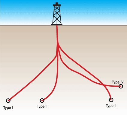
- Type I – Build and Hold: This pattern employs a shallow initial deflection and a straight-angle approach to the target. It is most often used to reach single targets at moderate depths, and sometimes for drilling deeper wells with large horizontal departures.
- Type II – Build, Hold and Drop (“S” pattern): After a relatively shallow deflection, this pattern holds angle until the well has reached most of its required horizontal displacement. At that point, angle is reduced or brought back to vertical to reach the target. The Type 2 pattern is most applicable to wells exposing multiple pay zones, or wells subject to target or lease boundary restrictions.
- Type III – Continuous Build: Unlike the Type 1 and 2 patterns, this trajectory has a relatively deep initial deflection, after which angle is maintained to the target. The continuous build pattern is well-suited to salt-dome drilling, fault drilling, sidetracks and redrills.
- Type IV – Build, Hold and Build: This is the general pattern describing horizontal wells. The decision to drill horizontally is primarily based on reservoir engineering and reservoir management considerations.
Having established a basic well profile, the next step is to plan the trajectory in detail, again starting with the bottom hole target (Figure 2, Directional drilling parameters).
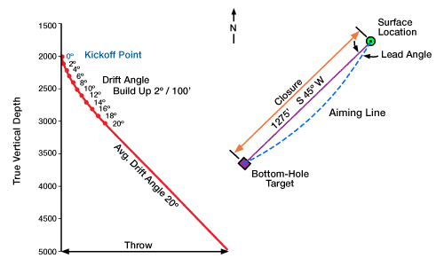
- We express the target location in terms of its true vertical depth (TVD) and horizontal departure, or throw.
- The target diameter or radius dictates how much control we have to exercise over the well trajectory. Generally, the greater the degree of control, the higher our drilling costs. We should therefore establish the largest target that will ensure our meeting well objectives.
- Except for the special case of slant drilling, all wells start off as more or less vertical. They become directional only when we reach the kick-off depth (KOD): the point at which we begin the incremental building of drift angle, or inclination from vertical. Inclination is expressed as degrees per unit of drilled interval (typically
 or
or  ).
). - The turn-off depth (TOD) is a point at which we change the hole direction, or azimuth, as measured with respect to true North. For example, if a target is located at a direction of 20° from North in relation to the surface location, the azimuth at the turn-off depth is N20°E.
- The build-rate angle and drop-rate angle, respectively, refer to the incremental increase or decrease in inclination from vertical, while the turn-rate angle is the change in azimuth per 100 feet or meters of hole section.
- Because of drill string rotation, bits tend to “walk” to the right in the horizontal plane. To account for this natural drift, it is common to initiate the turn of the well path with a specified lead angle (LA) to the left of the target. The required magnitude of the lead angle is generally determined from offset well records. Because bits also tend to “fade” (i.e., lose angle due to gravity); the lead angle should therefore be high with respect to the average angle.
This section summarizes the equations used to calculate directional plans in the vertical plane for the Build and Hold, Continuous Build and Build, Hold and Drop well patterns. The reader may find derivations for these equations in Maurer (1966).
Build and Hold Pattern
Calculation of the Build and Hold pattern requires the following data (Figure 3):
(KOD) = kick-off depth, ft
(HDY)t = target horizontal departure in the y plane, ft
(TVD)t = true vertical depth, ft
BR = build rate angle (°/ft)
Rb = build radius (ft or m)
t = total depth
b = build
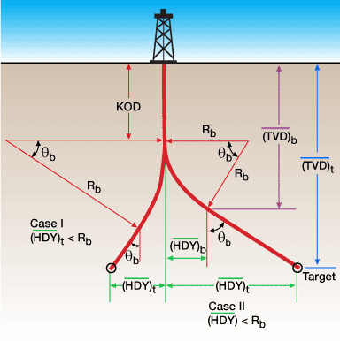
Case 1: (HDY)t < Rb
![]() (1)
(1)
![]() (2)
(2)
where
![]()
![]()
θb= maximum angle of hole inclination at end of build.
The total measured depth to target (TMD) equals
![]() (3)
(3)
and we can calculate kick-off depth as
![]() (4)
(4)
Case 2: (HDY)t > Rb
![]() (5)
(5)
TMD and KOD are as defined in Equations 3 and 4.
Continuous Build Pattern
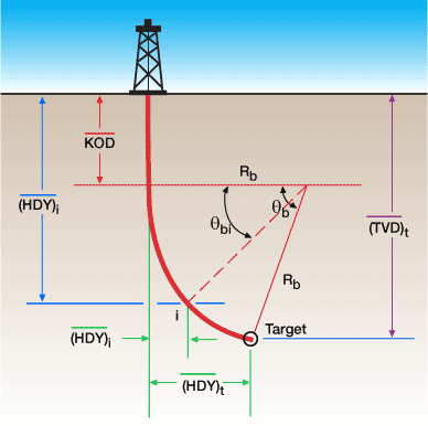
The data required for the Continuous Build calculation (Figure 4) are the same as those required for the Build-and-Hold equations. The calculated horizontal departure in the y plane and the true vertical depth at a point i along the build section are as follows:
![]()
![]()
The total True Vertical Depth (TVD)t and the Total Horizontal Departure (HDY)t can be found by substituting the total build angle, θb, in Equations 5 and 6, respectively.
The total Measured Depth is given by
![]()
Build, Hold and Drop Pattern
Data requirements for the build, hold and drop pattern (Figure 5) are similar to those for the Build and Hold and Continuous Build patterns. The following equations are used to calculate the maximum angles of inclination:

Case 1: Rb < (HDY)h; Rb+ Rd > (HDY)t
![]() (9)
(9)
Case 2: Rb< (HDY)h ; Rb+Rd <(HDY)t
![]() (10)
(10)
The Total Measured Depth is
![]() (11)
(11)
The calculations that define the well path in the horizontal plane can be described by the following equations:
![]() (12)
(12)
![]() (13)
(13)
The incremental True Vertical Depth is
![]() (14)
(14)
where
![]() = incremental distance measured along north-south direction
= incremental distance measured along north-south direction
![]() = incremental distance measured along east-west direction
= incremental distance measured along east-west direction
![]() = an assumed incremental distance of hole section (generally 100 ft)
= an assumed incremental distance of hole section (generally 100 ft)
![]() ;
; ![]() = inclination and azimuth at previous station (i−1)
= inclination and azimuth at previous station (i−1)
We may find the total distances by summing the total increments:
![]() (15)
(15)
![]() (16)
(16)
![]() (17)
(17)
 Petro Shine The Place for Oil and Gas Professionals.
