Related Articles


Completion Applications: Sanding
Solids production, or sanding analysis, and hydraulic fracture design are the two main geomechanics applications related to reservoir completion, and are localized to reservoir intervals.
Sanding refers to the unwanted production of solids along with hydrocarbons. Solids production is a challenge in high-porosity, low-compressive strength reservoirs and is generally restricted to the near-wellbore region, but sometimes it can affect entire reservoirs.
These excess solids cause erosion of surface equipment and failure of downhole completions. In severe cases, casing erosion leads to the collapse of the well or solids filling the well for a thousand feet or more, both leading to significant loss of production. Initially, solids production may not be an issue but may become a problem later in the life of a field when water breakthrough occurs or when reservoir depletion has reached a critical state.
Methods for dealing with solids production are classified as exclusion methods or prediction methods. The most common exclusion method, gravel packing, is designed to prevent sand from entering the wellbore. Prediction methods try to prevent failure of the reservoir by managing production rates. Both methods reduce production rates, creating an economic incentive to predict when sand control is required and what methods to employ.
Borehole Environment
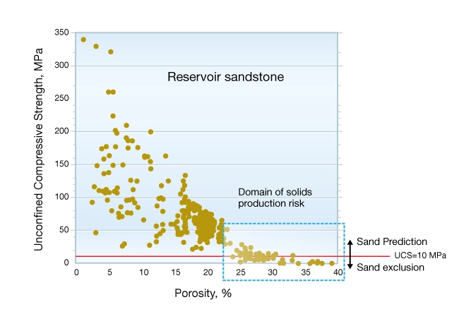
Reservoirs that are prone to solids production tend to be high porosity, over-pressured, poorly consolidated, and poorly cemented. Figure 1 is a plot of the unconfined compressive strength (UCS) of sandstone versus porosity illustrating the range of rock strengths pertaining to the solids production problem (lower right). Two rock strength domains are identified with a red line plotted at UCS = 10 MPa. Reservoirs with UCS falling below the line are normally completed using sand exclusion methods. Those plotting above the line typically use sand prediction techniques.
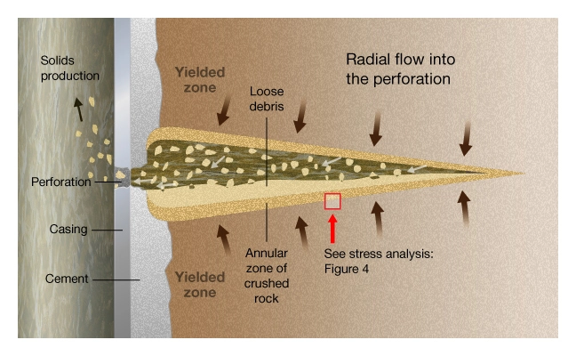
Solids production is a two-stage process: first the rock must fail and then the failed material must be transported from the perforation tunnel into the wellbore. Failure is defined as breaking cement bonds between the grains, grain crushing, or both; transport of solids is governed by production rate.
Figure 2 shows a schematic cross-section through a typical perforation in sandstone. The salient features are a zone of yielded rock near the casing, an annular zone of crushed rock adjacent to the wall of the perforation tunnel, and a pile of loose debris at the bottom of the tunnel. Solids production can only occur if the rock around the tunnel has failed and rock fragments are transported to the well.
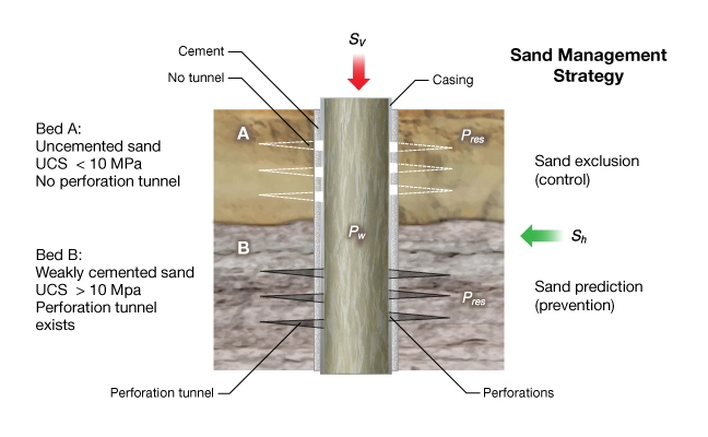
The first task for the geomechanics team is to determine the relative strengths among the reservoir strata to be completed. Figure 3 is a schematic of a cased and perforated completion in a low-strength reservoir showing two beds, A and B.
- Bed A is a weak uncemented sand, under in-situ stress conditions and is not strong enough to support a perforation tunnel.
- Bed B represents weakly-cemented sandstone that is strong enough to support a tunnel.
If all the reservoir intervals are as weak as Bed A, the decision would be to complete the zone using a sand exclusion method, such as a gravel pack or a fracture-pack, discussed later. If strong and weak rocks are interbedded, selective perforation of the stronger intervals can be an appropriate strategy. Where the rocks are of uniform and sufficient strength, a reservoir stress management strategy should be used to avoid failing the rock, that is, limit the drawdown pressure to prevent sanding.
Mechanics of Sanding
The following analysis illustrates the basic mechanics governing initiation of solids production in reservoirs strong enough to support a perforation tunnel. These are reservoirs that can benefit most from solids production risk analysis, thereby avoiding unnecessary gravel packing. Because of the economic impact of an incorrect completion decision, a rigorous numerical analysis is conducted for these reservoirs. A good introduction to the numerical analysis of the sanding problem can be found in papers by Morita et al. (1987).
The objective of predicting solids production is to estimate the maximum drawdown or how much the wellbore pressure can be reduced ( ), without collapsing the perforation tunnels. As with wellbore stability, knowledge of the applied principal stresses, pore pressure, and rock strength are required to predict rock failure. Figure 4 shows a stress analysis of a horizontal perforation for undamaged rock outside of the zone of crushed rock created during the perforating process. Shown from left to right are:
Stress Analysis of a Horizontal Perforation
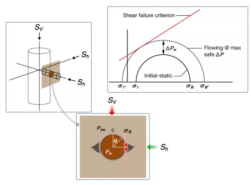
1. The geometry of the problem.
2. The stresses in the plane normal to the perforation axis and mode of failure.
3. A Mohr’s circle diagram of the stresses before and after drawdown of the well. At sufficient drawdown, ΔPw, the tunnel walls fail in shear, thus increasing the probability of solids production. The solid circle represents the initial stress after perforating but before drawdown. The dotted circle shows the state of stress corresponding to the maximum safe drawdown pressure.
In this example, it is assumed that  and that
  .
.


Drawdown causes a reduction of  and increases the magnitude of \( \sigma _{\theta} \), thereby increasing the diameter of Mohr’s circle and moving the walls of the perforation tunnel closer to shear failure. The center diagram shows shear failure at the sides of a horizontal perforation tunnel. As was the case for wellbore stability, certain orientations of the perforations are more stable than others. The same basic analysis applies to perforations—find the orientation where the shear stresses on the walls of the perforation are minimized.
Often solids production only develops after the reservoir has been on production for a period of time. Production reduces the magnitude  and
and  leading to an increase in
  on the tunnel. If initial production is solids-free, there may come a time where the tunnels fail.
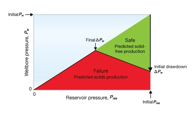
A perforation stability analysis is shown schematically in Figure 5. The green shaded region represents the predicted maximum safe drawdown for solids-free production as a function of reservoir pressure. The pressure axis pertains to a specific wellbore and reservoir with initial pressure . The boundary between the red and green fields pertains to a particular set of model parameters: perforation orientation, rock compressive strength, and earth stresses. Note that the maximum safe drawdown decreases with decreasing reservoir pressure. For an example of how safe drawdown varies with orientation of the perforation axis, see Venkitaraman et al., 2001.