Related Articles

Learning Objectives
After completing this topic “Hydraulic Fracturing Fundamentals“, you will be able to:
- Summarize the purpose and history of hydraulic fracturing and identify some modern day hydraulic fracturing operations.
- Summarize the fundamental concepts, applications, and design considerations of hydraulic fracturing.
- Summarize the key points of fracture initiation, growth and barriers.
- State how rock matrix and mechanical properties affect fracture treatment design.
- Compare the in-situ testing methods for determining initiation, propagation, and closure pressures.
- Compare the quantitative and qualitative models for describing fracture growth.
- Describe direct and indirect techniques for fracture treatment diagnostics.
Hydraulic fracturing is a type of well stimulation treatment designed to bypass near-wellbore formation damage and create an improved fluid flow path from the reservoir to the well.
A typical fracturing treatment involves:
- Creating a crack or fracture in the rock matrix by pumping fluid at a high rate and pressure
- Extending or propagating the fracture through continued pumping
- Holding the fracture open by pumping a fluid laden with solid proppant particles
Depending on the treatment volume, the created fractures may be relatively short in length, and designed mainly to bypass near-wellbore formation damage. Or they may extend hundreds or even thousands of feet into the formation, creating high-permeability flow channels for the reservoir fluid. In either case, the primary treatment objective is to improve the well’s productivity index.
Since its first use in 1947, hydraulic fracturing has become a dominant completion technique, with over 2.5 million wells having undergone fracturing worldwide (King, 2012).
- In the United States alone, more than 1.1 million separate and successful hydraulic fracturing treatments have helped deliver over 600 trillion cubic feet of natural gas (Halliburton, 2016). Today, nearly nine out of ten onshore wells in the USA require fracture stimulation to become or remain economically viable.
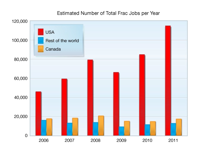
- Hydraulic fracturing has also been widely used in developing Canada’s shale gas resources and Russia’s conventional oil reservoirs. It is also being applied in carbonate formations in the North Sea, Mexico’s Bay of Campeche, Brazil’s Espirito Santos Basin and the Arabian Gulf. In 2011, more than 140,000 hydraulic fracturing treatments were performed worldwide (Figure 1).
Designing a successful hydraulic fracturing treatment requires, at a minimum, knowledge of reservoir engineering, the nature of fluid flow in porous media, rock mechanics, fluid rheology, fluid mechanics, and fluid chemistry. Implementing a large volume fracturing job is a major logistical undertaking that can involve dozens of vehicles, tons of proppant and millions of gallons of fluids.
The Hydraulic Fracturing Process
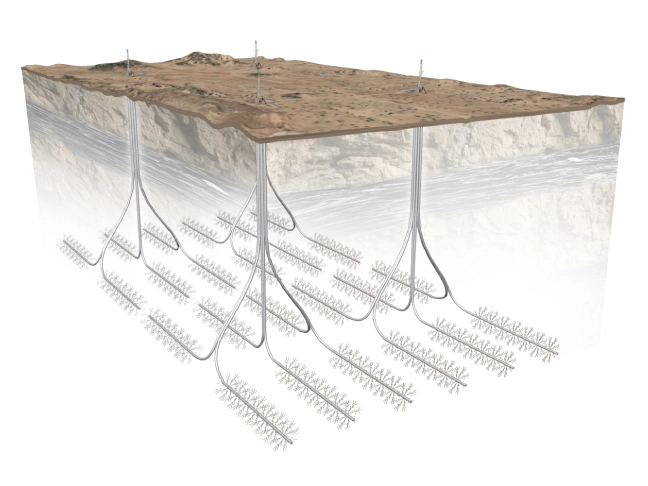
A good example of the hydraulic fracturing process and its application is the Marcellus Shale in Pennsylvania, USA. A typical Marcellus Shale well is drilled horizontally and fractured in multiple stages along its horizontal section. This creates a series of vertical fractures extending hundreds of feet on either side of the wellbore. Because wells are drilled parallel to one another from a single well pad, the arrangement of hydraulic fractures is designed to create a wide network of pathways for natural gas to flow from a shale formation that would otherwise not produce at economic rates (Figure 2). In the Marcellus Shale it can take 2-3 days to fracture a single well and 10-14 days to fracture multiple wells on a pad.
The hydraulic fracturing process involves blending proppant (typically sand), primary fracturing fluid (liquids, gases or mixtures of the two), and chemical additives, and pumping this mixture into the well using high pressure positive displacement pumps (Figure 3). A number of pumps can be combined to achieve the horsepower needed to deliver the mixture to the bottom of the well at the rate and pressure required to fracture the formation.
The entire operation is typically monitored from a control van, where all of the data from a variety of sensors are collected and analyzed, and from where the various components of the blending and pumping systems are controlled. It is critical that the job follows a strict time schedule; delays or interruptions can lead to treatment failure or well damage.
The treatment design usually calls for pumping fluid in stages:
- First, a fluid containing no proppant is pumped to initiate the fracture.
- This fluid is followed by the proppant-laden fluid.
- Fluid without proppant is then used to displace the proppant into the fracture.
In this type of multi-stage pumping operation, close monitoring and control of volumes, rates, and pressures is critical. In the Marcellus Shale, multiple wells are sometimes fractured in a sequence that involves alternating the pumping of fluids into first one well and then another (Figure 3). This presents logistics, monitoring, and control challenges, but if done properly can save time and money.

When the fracturing treatment has been completed, the pumps are shut down and the well is shut in for a period of time. The well is then allowed to produce, and some of the injected treatment fluid flows back to the surface. An important consideration in the hydraulic fracturing process is how to handle this fluid. Even though much of it remains in the formation, a considerable amount can flow back along with the formation fluid over a period of days, weeks or months. This produced fracturing fluid must be handled carefully, treated for reuse or transported to disposal wells and injected for disposal (Figure 4).