Related Articles

Learning Objectives
After completing this topic “Structural Interpretation“, you will be able to:
- Determine the location of favorable traps for hydrocarbon accumulations.
- Discuss how the change of thickness along a geological formation will cause the reflections to change the character of a wavelet.
- Outline the need for migration in complex structural geometries due to difficulties with reflector correlation.
- Explain the timing and the depositional mechanics of faulting and how this impacts oil and gas migration.
- State the different types of seismic effects that can be misleading during interpretation.
- Describe why we have no interest in traps which formed after the migration of hydrocarbons was complete.
Introduction to Structural Interpretation
The initial goal of seismic structural interpretation is to determine the location of favorable traps for hydrocarbon accumulations.
The first step is to determine the most continuous reflectors. These are then color-coded and correlated to the other seismic lines in the grid. Intersecting lines should show the same reflectors at the same time, at least at the intersection points. These reflectors must be correlated to existing well logs and will be identified geologically, in terms of age and lithology.
From sonic logs, synthetic seismograms can be constructed and these are used to predict the location of seismic horizons for interpretation.
Initially, contour maps are produced in two-way reflection times. With the help of reflection surveys and sonic logs, velocities can be obtained, and then structural contour maps in depth can be produced.
Lateral velocity variations due to lithological changes in the subsurface can produce discontinuous or uncorrelatable reflectors. In Figure 1, the continuity of the indicated horizon gap can be established by referring to the strength of the reflection, the dip above and below the incomplete area, and the parallelism of the top and bottom reflectors.
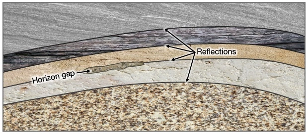
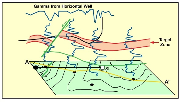
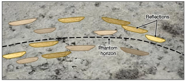
Figure 2 shows an example of a natural discontinuity of sand lenses. A phantom horizon can be drawn to establish a common tendency of the discontinuous lenses.
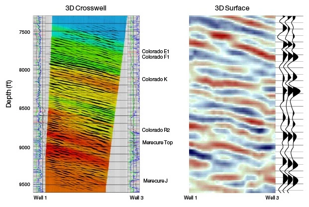
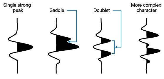
Another way of correlating reflections of doubtful continuity is to analyze the characteristics of the seismic trace. Figure 3 shows the shape of several seismic traces. Seismic traces are composed of wiggles made up of different combinations of peaks and troughs. A specific character that repeats laterally is normally an indication that they are generated by the same reflector.
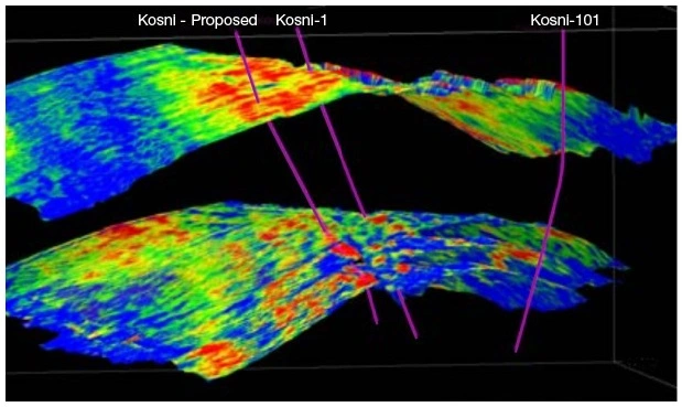
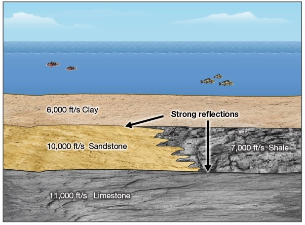
Lateral variations, like the image shown in Figure 4, must be analyzed very carefully before giving a definitive interpretation. In effect, lateral lithological changes imply lateral velocity changes and consequently changes in the velocity contrasts at the top and bottom of the layer. As a result, in these examples the larger reflections will come from the top of the formation, and from the bottom alternatively, if the velocity contrasts are large enough.
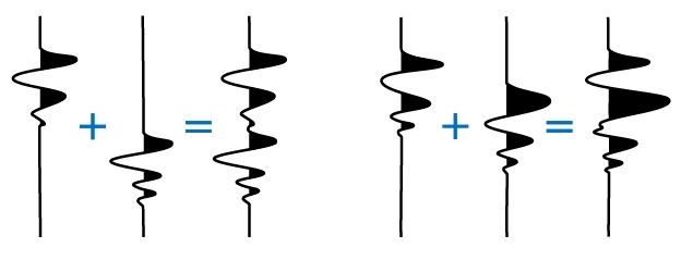
Another common case of difficult interpretation occurs with thinning horizons. The change of thickness along a geological formation will cause the reflections from the top and bottom of the layers intersecting at a point to overlap, resulting in the cancelling, reinforcing, or change of character of the reflections. Two examples of this are shown in Figure 5.
Difficulties for correlation are also quite common in complex structural geometries. An additional step called migration must be performed in order to position reflections in the right location at depth.
The difference of the reflection times of two reflectors can be contoured to produce isochronal maps, and, if the velocity between the two reflectors is known (interval velocity), then isopach maps can be produced.
Following are useful guidelines for a sound structural interpretation:
- Determine if the seismic lines you want to interpret have been migrated. This is important to know early in the process because structures will shift between non-migrated and migrated seismic. Compare non-migrated lines with migrated lines to understand the effects introduced by migration.
- Remember that the interpretation of seismic lines is done on time sections (at least as a first approximation). This can be misleading because the deformation of the vertical scale is not usually linear. The time-depth relationship is not a direct one. Each geological formation has a different seismic velocity, which makes the time-depth conversion a difficult task.
- In the case of extensional geologic environments, it is recommended to start with the highlighting of the obvious faults. In the case of compressive geology, sequence stratigraphy interpretation should be conducted before structural interpretation. The interpreted stratigraphy will guide the reconnaissance of structures and the chronologic cataloging of events.
- For land surveys, it is important to review the location map of the survey and surface geology maps to understand the regional context. Frequently, bad data can be explained by surface conditions. Surface outcrops are certainly the best guide to understanding the subsurface, with due considerations of scaling factors.
- Interpretation should start in the undisturbed areas and then move into the more complex structures.
- Attention should be given to the cause of the unconnected reflectors that are identified by divergent reflections. Faults are always associated to some type of detached reflectors.
- Faults are characterized by displaced reflections that need migration. It is important not to extrapolate the fault in noisy areas of the seismic section as this can lead to incorrect conclusions. Normally faults end in some detachment surface where no more displacement is visible.
- Attention should be given to different types of seismic effects that can be misleading for the interpretation. These might include multiples, migration effects, diffractions, velocity effects like “pull-ups,” reflections from out of the seismic plane, etcetera.
- In cases of complex geology, it is advisable to produce different versions of the interpretation that may account for plausible, interpretation scenarios. Then additional information (structure maps at different horizons, thickness maps, etcetera) should be produced to identify the interpretation that best fits the available data.