Related Articles

Erosional Channels
Some tasks of the interpreter are now apparent:
- To pick the sequence boundaries (which are unconformities or their correlative conformities).
- To classify the internal configuration of reflections within the sequence (conformable, divergent, sigmoid, oblique, hummocky, chaotic, and so on).
- To recognize the depositional and erosional setting of the sequence from its context in the section (open basin, shoreline, prograding shelf, continental, local sediment source, etcetera).
- To infer what type of rocks would be expected within the sequence.
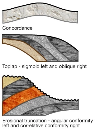
It’s important to understand the different depositional sequence types that can occur at the top and base of boundaries. Figure 1 shows the reflection relationships which can occur at the base of a sequence.
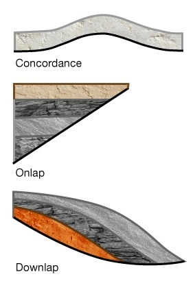
Figure 2 provides the same relationship for those at the top of a sequence.
We can illustrate the interpretation approach with some examples of erosional channels. These may be cut by rivers, glaciers, or by marine currents.
Channel Examples
Figure 3 illustrates a channel cut by a river. We see how the flanking reflections are breached by the channel, and how the channel has become filled with sediment of quite different genesis. In fact, the sediment in this case is of glacial origin, and higher in velocity than the surrounding rocks because we notice the velocity pull-up in the reflections below the channel.
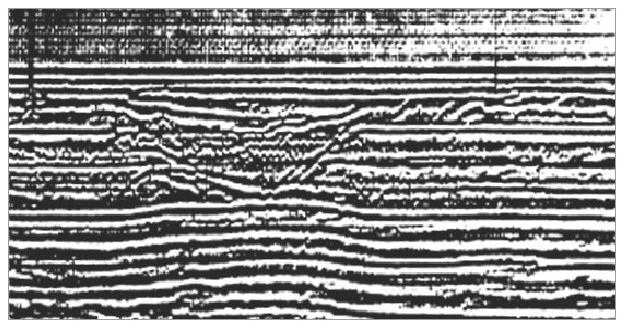
Figure 4 shows us that marine currents, even in a deep open basin, can cause dramatic erosion. In this case, the channel is full of water, of a velocity lower than the surrounding rocks, which we can see from the velocity pull-down in the reflections below.

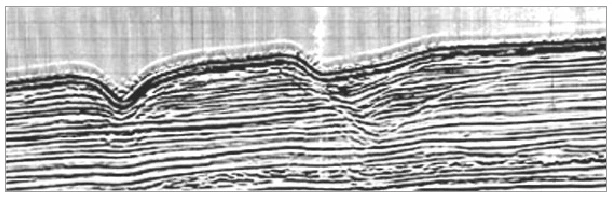
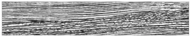
Figure 5 illustrates a similar channel cut in past geologic time. Channels cut by rivers often have rough, steep sides. They may contain chaotic fill of terrestrial origin or, if they have been inundated by the sea, marine sediments onlapping the channel walls. Channels cut by marine currents tend to be smoother. In the case of Figure 5, the filling sediments onlap the channel walls very clearly.
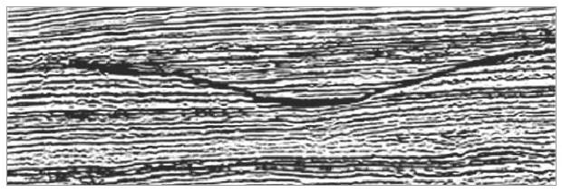
Figure 6 illustrates that marine channels may remain static (as at the left) or they may prograde. The right channel is continually eroding away at its left bank and depositing sediments on its right bank, much as a meandering river erodes its outer bank and deposits a point bar on its inner bank.
A counterpart to Figure 6, but in past time, is seen in Figure 7. The channel fill has two components: chaotic sediments on the right, deposited by the channel itself as it prograded leftward, and orderly marine sediments which onlap the final right wall of the channel and drape significantly into the channel.
Drape is a useful tool as it allows us to characterize rocks by their resistance to compaction. The value of this is that clays and shales are notably more compactible than other rock types. In Figure 7, the marine fill thickens where the channel is deepest; compaction soon after deposition has allowed more deposition. The interpretation is that the layers showing the thickening are rich in shales. In contrast, in Figure 5, there is no drape into the channel; the fill is less compactible, and we expect less shale content.