Related Articles


Mechanical Earth Model MEM Workflow
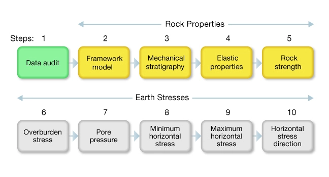
The MEM workflow is represented as a series of ten interdependent steps. The sequence reflects a logical progression of data processing; each step builds upon one or more previous steps. Figure 1 shows the recommended sequence for building an internally consistent MEM.
There are three levels of complexity associated with constructing a MEM, with Level 1 models being the least complex and Level 3 the most.
- Level 1 projects have all the information required to construct and calibrate the MEM available in a single well.
- Level 2 projects have gaps in the data. For example, a shear wave log might be missing or the density profile does not extend to the surface. Such projects require you to construct the missing data from offset wells or to model data using geologic information and petrophysical theory.
- Level 3 projects are intense high-pressure projects. They are best characterized as real-time modeling where the outcome, a drilling program for example, depends on the accuracy of the geomechanical model.
The following steps are based on a Level 1 model for an isotropic elastic earth where  is a principal stress.
Process for Level 1 Mechanical Earth Model
Step 1: Data Audit
A data audit is a critical project planning tool (Figure 2). This step involves collecting the geological, seismic and drilling data, borehole measurements, and rock sample information. In addition to collecting data, the audit establishes which information is available for constructing a geomechanical model, which data are missing, and what steps are required to fill any data gaps. The audit defines the complexity, time, and human resources needed to complete the project.

Rock Properties
Step 2: Framework Model
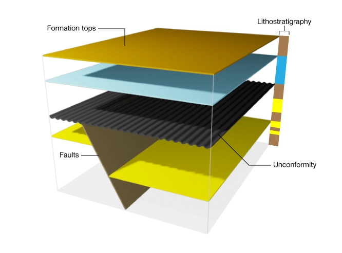
The framework model captures information about the contemporary stress regime and the geologic history of the location. This model provides guidance as to what to look for in the data when constructing the MEM. Is the region tectonically active or inactive? Are the rocks poorly consolidated or well lithified? Are there any major unconformities? Are there any faults or fracture zones?
Imagine that the framework model depicted in Figure 3 is a schematic derived from interpretation of 3D surface seismic data. This model shows that the region was once in an extensional tectonic regime but that faulting is now inactive. If the rocks were brittle at the time of faulting, it is expected that natural fracture intensity will increase approaching the fault. Below the unconformity, the contemporary stress regime might correspond to final stages of an extensional regime. Above the unconformity, uniaxial strain conditions might apply. If the contemporary direction of  is in the fault dip direction, then the contemporary and paleo stress regimes might be similar. If the interval in sedimentation was long, the diagenesis of sediments above and below the unconformity could be very different. This observation anticipates the possibility that elastic and strength properties could be different across this boundary. The foregoing line of reasoning helps guide you to produce an internally consistent MEM.
Step 3: Mechanical Stratigraphy
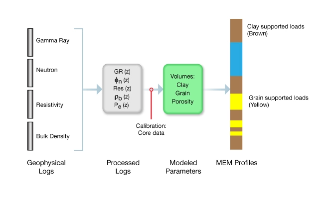
Information about the lithostratigraphy is used to build the mechanical stratigraphy. The mechanical stratigraphy classifies strata according to the nature of the continuous load-bearing solid phase, either grain-supported or clay-supported facies.
Construction of a mechanical stratigraphy from geophysical log data is illustrated in Figure 4. Shown are the normal geophysical inputs to a petrophysical volumetric analysis. Log data processing includes editing and depth shifting, computing volume fractions of clay, other rock forming minerals, and porosity. The mechanical stratigraphy is then represented as a three component rock comprising pores, clastic grains, and clay minerals such that:  . The rock column is then subdivided into grain-supported and clay-supported facies according to volume fraction of clays in each layer. Typically clay supported facies are defined as those where
  35 – 40% and grain supported facies are those with lower clay volumes.
Step 4: Elastic Properties
Elastic property profiles, Young’s modulus ( ), and Poisson’s ratio (
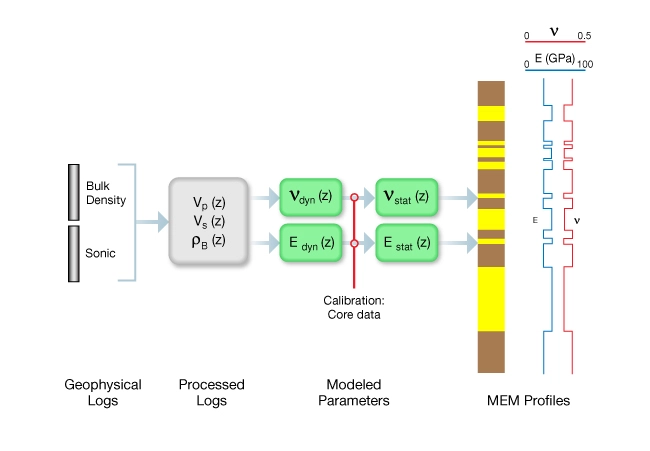
 ), are calculated using sonic and density log data. Figure 5 illustrates the process of constructing these profiles. Sonic logs are processed to generate depth profiles of compressional
  and shear
  wave velocities. These are edited and depth-shifted to the density log so that they can be used to compute the dynamic elastic parameters using rock mechanical property equations. In high-porosity fluid-saturated rocks, dry-frame moduli are computed. Dynamic Young’s modulus and Poisson’s ratios are then converted to the static values using a generic correction or, where possible, a locally-derived calibration.
Elastic property profiles are shown schematically on the right in Figure 5. The step-like character of these and subsequent profiles reflects the influence that mechanical stratigraphy has on the modeled elastic properties. Actual data rarely show such pronounced steps because the rock composition and texture often are more gradational. Preserving the step-like profile is a reminder that the MEM is a model.