Related Articles

The Mechanical Earth Model (MEM)
This course looks at construction of a one dimensional Mechanical Earth Model (1D MEM). We begin by defining the mechanical earth model and its purpose. We then review a workflow for constructing a model using geophysical log data. The first three steps of this workflow set the context for modeling the MEM profiles in steps 4-10. Throughout this discussion, we employ a common format to describe building a profile. This includes:
- Specification of input geophysical logs
- Identification of processed data
- Modeling of processed data to produce each MEM profile
Where appropriate, we refer to methods for calibrating the profiles. Finally, we introduce the concept of feedback loops as a means for validating and updating the model.
The MEM is a numerical representation of all geomechanics knowledge available for a field or basin. Its primary purpose is to provide structured information used in geomechanical analysis and modeling. As stated previously, and represented again here in Figure 1, the MEM spans the entire stratigraphic section penetrated by wells and includes the following components:
- Framework model
- Mechanical stratigraphy
- Rock mechanical properties (
 ,
,  , UCS, FA)
 - Earth stresses (
 ,
,  ,
,  ,
,  , azimuth)
 ,
,  , UCS, FA)
 ,
,  ,
,  ,
,  ,
, 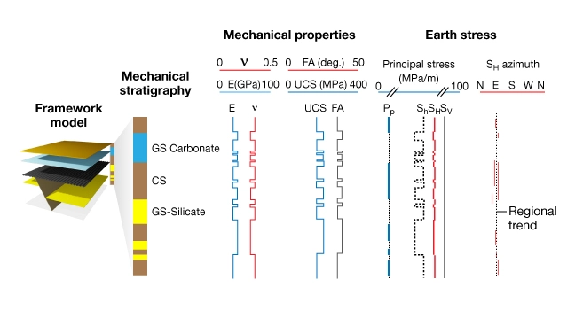
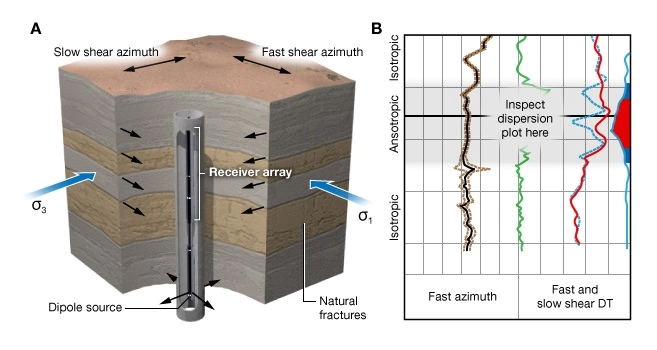
The framework model and mechanical stratigraphy provide the context for developing MEM profiles (components 3-4 of the model). The framework model captures information about the geologic structure in the MEM. It is based on a structural geologic interpretation of 3D seismic data and includes formation tops and faults. The style of faulting, if present, constrains the contemporary and paleo states of stress.
Mechanical stratigraphy is fundamental to building profiles of geomechanical properties. It divides the lithostratigraphy into groups of rock that are expected to deform in a similar manner. The basic model is a two component mechanical stratigraphy, consisting of rocks classified according to the composition of the continuous load-bearing solid phase, which are made of either detrital grains (GS; grain-supported facies) or clay minerals (CS; clay-supported facies). This classification segregates rocks into groups that are expected to deform in a similar manner, and identifies those that may react with drilling fluids.
In this course, we identify common sources of oil field data used to construct a geomechanical model. We begin by introducing the mechanical earth model concept as a way to explain what specific data are needed. We then list sources of data in the order that new knowledge about a subsurface volume is normally acquired. Sources include:
- Geological model
- Seismic data
- Drilling data
- Borehole measurements
- Rock samples
We discuss each source’s contributions to the model separately and summarize them in tabular form.
The focus is on field-scale models with dimensions measured in kilometers. Figure 2 shows a subsurface volume partitioned into three spatial domains:
- Overburden
- Reservoir
- Underburden
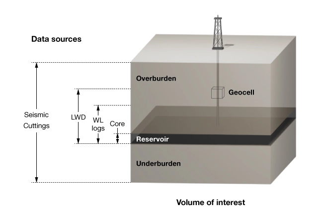
Each domain is populated with data from different sources. Figure 2 illustrates the spatial distribution of five primary sources of geomechanical data. Geologic and seismic data contribute over the entire volume. Drilling and LWD data are primary sources in the overburden. Drilling data, wireline measurements, and rock samples provide the bulk of data in the reservoir section. Rock samples are used for lab testing of mechanical properties in the reservoirs section.
Geomechanical models of the near wellbore region have the highest spatial resolution and the greatest accuracy in the reservoir intervals. However, lower-resolution field-scale models are valuable for drilling, planning and execution, and field development planning.
The most predictive earth models are internally consistent. Recall that the geomechanical model characterizes the state of stress and rock mechanical properties of a specific volume of rock. If, for example, the rock is quartz sandstone with a porosity of 10%, then all the mechanical properties are consistent with that rock type and porosity—the rock would not be described as weak or ductile.
Another example has to do with computing MEM profiles. An inconsistent model uses one bulk density profile to compute the vertical stress and a different profile to compute elastic properties. Similarly the pore pressure profile used to compute effective stress should be the same as the one used to specify the safe mud weight window in a wellbore stability analysis. If there are multiple interpretations of any variable, they should be reconciled before used in a stress calculation or other geomechanics applications. If they are not reconciled, the uncertainty should be carried forward into all subsequent calculations requiring that variable. Otherwise valuable time is lost when trying to diagnose a geomechanical problem.