Related Articles


Completion Applications – Hydraulic Fracturing
Hydraulic fracturing is a method for obtaining economic production from low permeability reservoirs, such as tight gas sands and shale gas reservoirs, and to enhance recovery in aging oil fields. Unlike reservoirs prone to solids production, these reservoirs have low porosity and high compressive strength. And hydraulic fractures are not restricted to the near wellbore region but often extend hundreds of meters vertically and laterally away from the wellbore.
This section discusses applications of geomechanics to the design of hydraulic fractures starting with fracturing a stratified reservoir from a vertical well.
Objectives of Reservoir Stimulation by Means of Hydraulic Fracturing
Hydraulic fractures increase productivity by creating a large area of contact with reservoir rocks. Two primary objectives of fracture stimulation are to:
- Maximize the area of contact between the fracture and the reservoir,
- Achieve and maintain a high-conductivity flow path along the fracture to the wellbore (Economides and Nolte, 1987).
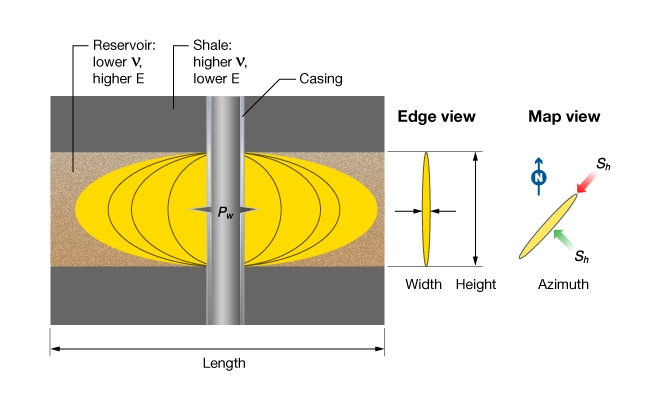
Figure 1 shows an idealized hydraulic fracture in a reservoir bounded above and below by shale. The four primary unknowns of hydraulic fracture design are identified: height, length, width, and orientation.
Mechanics of Hydraulic Fracturing
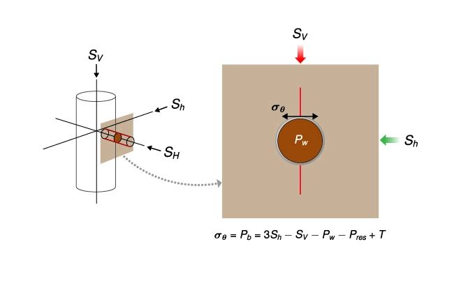
The process of hydraulic fracturing is to increase pressure in an isolated section of the well until the formation breakdown pressure is reached, creating a mode 1 fracture. The induced fracture propagates away from the well provided that fluid is injected at the fracture propagation pressure. In an ideal homogeneous, isotropic, unfractured rock, the induced fracture will propagate in a vertical plane oriented perpendicular to the least principal stress  . Figure 2 shows the borehole stress concentration governing the breakdown pressure and propagation direction of hydraulic fractures initiated from an openhole completion.
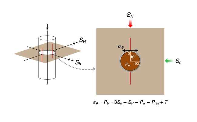
The diagram of the openhole completion (left) illustrates the magnitude and orientation of the hoop stress concentration at the fracture initiation pressure,  , (right). The induced fracture propagates as a mode 1 extension fracture in a plane perpendicular to (red line).
Two fractures initiate at the azimuth of the maximum horizontal stress where the hoop stress is a minimum ( and
and  degrees). Fractures propagate perpendicular to because it is the path of least resistance. The optimal reservoir contact area is achieved when the fracture is contained in the reservoir interval.
To achieve the second objective of maintaining a high conductivity flow path, the fracture must remain open after pumping stops. This is achieved by pumping proppant as the fracture is extended away from the wellbore. When pumping stops, fluid leaks off into the reservoir and the fracture begins to close. The proppant prevents the fracture from closing completely, thus creating the conductive flow path. (Mader, 2012).
Fracture width is governed by excess pressure,  , and the static Young’s modulus,
  . For example, the width of a circular crack of radius
  is given by:

For a given excess pressure, fracture width decreases with increasing Young’s modulus but is relatively insensitive to Poisson’s ratio,  (Smith et al., 2001). If reservoir rocks are isotropic, there is no directional dependence on . However, if the rocks are transversely isotropic, Young’s modulus measured in the plane of bedding is used to calculate fracture width.
Most commercial hydraulic fracture stimulations are performed through cased and perforated completions. Ideally, for a vertical well, perforation phasing is 180 degrees aligned with \( S_H \).
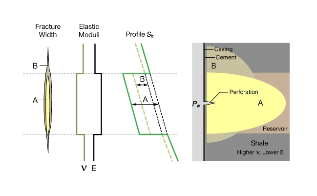
Figure 3 shows a diagram of a cased and perforated completion (left) illustrating the magnitude and orientation of the hoop stress concentration on a perforation aligned with \( S_H \) at the fracture initiation pressure, , (right). The induced fracture propagates as a mode 1 extension fracture in a plane perpendicular to (red line).

High breakdown pressures and poor proppant transport results when complex fractures form at perforations that are misaligned with the far field stresses. Correct stress direction and properly oriented the perforations is key to a successful fracture stimulation job.
The primary factor governing fracture containment is the stress contrast between the reservoir and the bounding beds. When the contrast is high, the fracture is contained. When the stress contrast is low, height growth will occur, wasting fluid and proppant on unproductive zones.
Figure 4 shows two schematic stress profiles through a sand-shale sequence, one with good fracture containment (A) and one with poor fracture containment (B), along with typical profiles of elastic moduli and corresponding fracture width.
The two fundamental requirements for containment are:
- The stress in the reservoir must be lower than in the bounding formation.
- The stress contrast needs to be sufficiently high; typically a 200 to 500 psi contrast is considered good but numerical modeling is required for a proper evaluation.
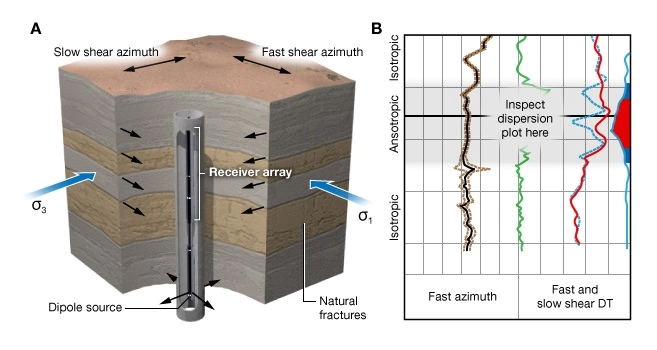
This example is idealized to identify the key geomechanical variables used in hydraulic fracture stimulation design. They are , , and stress direction. Vertical profiles of these parameters are required regardless of whether fracturing from open-hole, cased hole, vertical wells or horizontal wells. However, knowledge about spatial variability can also be very important when fracturing horizontal wells.
Anisotropy
Aggressive exploitation of shale-gas reservoirs in North America has highlighted the importance of elastic anisotropy on hydraulic fracture stimulation. Most shales are characterized by transverse isotropic elasticity with an axis of rotational symmetry perpendicular to layering, TI-V symmetry. For a TI-V material, there are now two different values for and . The primed parameters apply to vertical loading whereas the unprimed terms apply to horizontal loading.
Figure 5 shows the meaning of elastic moduli ,  , ,
, ,  for a TI-V shale. The primed moduli describe the material response to loading perpendicular to layering, and the unprimed moduli describe the response to loading parallel to layering.
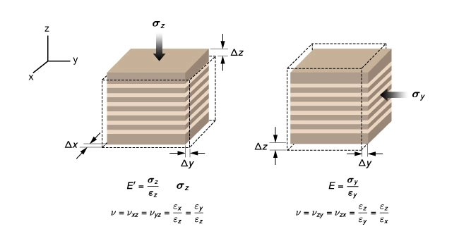
Young’s modulus in the plane of bedding () is greater than Young’s modulus perpendicular to bedding ( ), and the ratio of to can be more than 3:1. Neglecting anisotropy leads to errors in the estimate of fracture containment, fracture width, and predictions of proppant placement.
Anisotropy affects prediction of fracture containment because the vertical profile of the can be very different for anisotropic and isotropic formations. Horizontal stress predicted for a layered isotropic elastic earth subject to gravitational loading and tectonic stress is given by:

The analogous expression for layered TI-V rocks is:
![S_h - \alpha\, P_p = \dfrac{E}{E'} \left( \dfrac{\nu'}{1 - \nu} \right) \left [ S\nu - \alpha \left ( 1 - \xi \right )P_p \right ] + \dfrac{E}{1 - \nu ^{2}}\, \varepsilon _h + \dfrac{\nu E}{1 - \nu ^{2}}\, \varepsilon _H](https://petroshine.com/wp-content/ql-cache/quicklatex.com-fda2e710f28437ca030b828dd659f1ae_l3.png "Rendered by QuickLaTeX.com")
Figure 6 compares profiles of for a well drilled in the Baxter shale computed with and without accounting for elastic anisotropy. The anisotropic model predicts greater bed-to-bed stress contrasts and a generally higher level of stress over most of the interval.
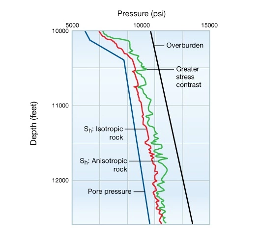 profiles for a well drilled in the Baxter Shale