Related Articles


Selection of Candidates for UBD
An important step in designing an underbalanced drilling operation is to select the appropriate technique and fluid system. As a starting point, recall that underbalanced drilling works to particular benefit in
- reservoirs that are prone to formation damage,
- low-pressure or depleted reservoirs,
- disposal wells.
If one or more of the above conditions applies, you should make an initial evaluation to select the appropriate underbalanced drilling technique and fluid type. This evaluation should use conventional drilling applications as a basis for comparison.
In some situations, the applicability of underbalanced drilling is not as clear-cut. Such situations might include:
- Low-pressure reservoirs with fractures.
- Very high permeability reservoirs.
- Extremely high-pressure formations.
These types of conditions require a more in-depth study of the circumstances and type of the proposed UBD technique.
Finally, there are certain conditions under which it is practically impossible to successfully apply UBD methods:
- Unconsolidated formations.
- Presence of swelling shale zones.
- Wellbore instability.
Which Underbalanced Technique to Use
There are set conditions that determine the applicability of different underbalanced drilling techniques. Table 1 shows the preferred techniques for various drilling conditions.
| Condition | Preferred UBD Technique |
|---|---|
| Low Rate of Penetration (ROP) through hard rock | – Dry air. – Mist, if there is slight water inflow. – Foam, if there is heavy water inflow. – Nitrogen or natural gas, if the well is producing wet gas. |
| Lost circulation through the overburden | – Aerated mud, if ROP is high or if water sensitive shales are present. – Foam, if wellbore stability is not a problem. |
| Differential sticking through the overburden | – Nitrified mud, if gas production is likely. – Aerated mud, if gas production is unlikely and an open surface system is to be used. – Foam, if pore pressure is very low and if the formations are very hard. |
| Formation damage through a soft/medium depleted reservoir | – Nitrified brine or crude with string injection or parasite string. – Foam, if the pore pressure is very low and an open surface system is acceptable. |
The following factors have to considered before deciding what type of underbalanced fluid to use:
- Presence of shales.
- Water production.
- Multiple zones with significantly different pore pressure.
- Possibility of sour gas production.
- Equipment availability.
The first step in selecting a UBD technique is to calculate the expected pressure profile within the wellbore. Borehole pressure limits should be based on the following factors:
- Pore pressure.
- Wellbore stability.
- Tensile failure.
- Shear failure.
- Matrix collapse.
- Chemical stability of shales.
It may not always be possible to accurately calculate the formation pore pressure. In such cases, offset well data and wireline logs should be used to obtain estimates.
Numerical mechanics modeling and field-testing should be used together in order to define stress fields around the wellbore. Bottomhole pressures should be kept within elastic stability limits defined by shear and tensile failure envelopes.
As soon as the wellbore instability and maximum pore pressure limits are determined, you may evaluate the different techniques by using the equivalent circulating densities of underbalanced drilling fluids (Figure 1: Underbalanced drilling fluid gradients) .
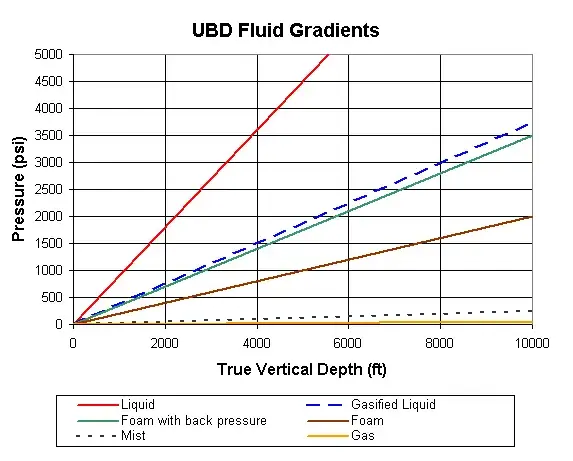
Since pore pressure gradients and formation strength can vary with depth, a limiting borehole pressure envelope should be constructed on top of the pressure gradient curves. The types of drilling fluids that are applicable at different depths can then be determined as shown in Figure 2, where the pore pressure gradient in a depleted interval reduces the maximum tolerable wellbore pressure.
When evaluating highly productive formations, a detailed numerical analysis of circulating pressures may be needed to estimate the ideal borehole pressures and production rates that would satisfy underbalanced conditions.
Water production makes gas drilling difficult because of mud ring formation. If water flows are encountered or anticipated, operations must be converted over to mist or foam. Also, the use of nitrogen or natural gas for mist drilling generally requires a high gas rate. Gas supply cost thus becomes a critical consideration in designing an underbalanced operation.
Mist and foam drilling generate similar volumes of wastewater. Therefore, if water disposal costs prevent the application of mist drilling then foam drilling probably will be also uneconomical.

Figure 2: “Tolerable Wellbore Pressure” representation example on fluid gradient chart.
Multiple zones
The presence of more than one permeable zone complicates underbalanced drilling operations, because the circulating pressure must satisfy pressure requirements of all permeable zones exposed to the wellbore. Formation fluids may flow from one permeable zone into another, resulting in an underground blowout. Since it is almost impossible to properly maintain different levels of underbalance at different depths under dynamic drilling conditions, the casing design should be such that the upper zones will be sealed off before penetrating the lower zones. Setting intermediate casing also prevents the possibility of fracturing openhole sections during well killing operations.
Hole geometry
It is quite difficult to keep uniform foam quality in deep wells, since additional backpressure may be needed to establish the necessary pressure gradient in the wellbore. Larger hole diameters require higher circulating rates for effective hole cleaning. Therefore, high viscosity fluids become more attractive as the hole diameter increases.
For hole diameters of 17½ in. [445 mm] and larger, stiffened foams and gasified liquids are recommended for improved cleanup efficiency. Some UBD equipment may be hard to obtain for larger hole diameters.
Underbalanced drilling fluid selection
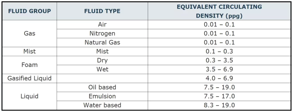
Based on their equivalent circulating densities underbalanced drilling fluids are classified into five major categories:
- Gas (Air, Nitrogen).
- Mist.
- Foam.
- Gasified Liquid.
- Liquid.
The selection of any of these fluids for underbalanced drilling operation can be a complicated process. Factors to consider in this selection process include:
- Reservoir rock/fluid properties.
- Fluid compatibility/characteristics.
- Hole cleaning.
- Bottomhole assembly.
- Type of data transmission.
- Corrosion.
- Temperature stability.
- Surface fluid handling and separation.
- Health and safety considerations.
- Environmental factors.
- Availability.
According to the UBD fluid guidelines published by the International Association of Drilling Contractors (IADC), drilling fluid selection is conducted in three stages:
Stage 1: What is the purpose for implementing underbalanced drilling?
Stage 2: What are the types of fluids that can be considered for underbalanced drilling?
Stage 3: Which fluid should be used for a given well?
Stage 1
The type of underbalanced drilling fluid to be used depends on the overall well objectives. At this stage, the lowest and highest pore pressures as well as the depth of target zone have to be identified. Borehole stability and anticipated production play a crucial role in defining the necessary pressure gradient (equivalent circulating density) to be established by the underbalanced drilling fluid.
Surface facilities and solids processing equipment have to be designed based on the expected amount of cuttings carried to the surface. The separation, storage and transmission of produced hydrocarbons while drilling should also be taken into consideration.
Stage 2
In selecting the appropriate fluid type, we may start with the IADC classification system for (Table 2) that defines a well’s risk level in terms of its performance characteristics.
| Risk Level | Identification |
|---|---|
| 0 | Performance enhancement only; no hydrocarbon containing zones. |
| 1 | Well incapable of natural flow to surface. Well is “inherently stable” and is low-level risk from a well control point of view. |
| 2 | Well is capable of natural flow to surface but enabling conventional well kill methods and limited consequences in case of catastrophic equipment failure. |
| 3 | Geothermal and non-hydrocarbon production. Maximum shut-in pressures less than UBD equipment operating pressure rating. Catastrophic failure has immediate serious consequences. |
| 4 | Hydrocarbon production. Maximum shut-in pressures less than UBD equipment pressure rating. Catastrophic failure has immediate serious consequences. |
| 5 | Maximum projected surface pressures exceed UBD operating pressure rating but are below BOP stack rating. Catastrophic failure has immediate serious consequences. |
We then need to estimate the maximum and minimum pressure limits for the formation using the pore pressure (maximum pressure limit) and the borehole stability criterion (minimum pressure limit) as described above. Figure 1 shows how these values are plotted in terms ECD for different underbalanced drilling fluids. Table 3 presents IADC classification of underbalanced drilling fluids and their corresponding equivalent circulating densities.
Selection of the drilling fluid also controls equipment requirements. Table 4 provides a brief summary of equipment requirements as a function of underbalanced drilling fluid group.
| FLUID GROUP | EQUIPMENT REQUIREMENTS |
|---|---|
| Gas Drilling | – For Air Drilling: Compressors, boosters, mist/foamer pump, blooie line, rotating head/diverter, flare/flame, drill string floats. – For Nitrogen Drilling: Cryogen tanks heaters – OR – membrane nitrogen generators, boosters, mist/foamer pump, blooie line, rotating head/diverter, flare/flame, drill string floats. – For Natural Gas Drilling: Pipeline / gas source, compressors, boosters, mist/foamer pump, blooie line, rotating head/diverter, flare/flame, drill string floats. |
| Mist Drilling | Source of gas, small injection pump, compressors, boosters, mist/foamer pump, blooie line, rotating head/diverter, flare/flame, drill string floats. |
| Foam Drilling | Source of gas, compressors, boosters, foam generator, blooie line, rotating head/diverter, flare/flame, special metering equipment, defoaming tank and pump, drill string floats. |
| Gasified Liquid Drilling | Gas/liquid separator, compressors, boosters, flare line, rotating head/diverter, flare/flame, drill string floats. |
| Liquid Drilling | – For Oil Based Drilling: Rotating head/diverter, drill string floats, cuttings disposal. – For Emulsion Drilling: Rotating head/diverter, drill string floats, cuttings disposal. – For Water Based Drilling: Rotating head/diverter, drill string floats. |
Stage 3
After collecting all the necessary information listed in the previous two stages, we select the best drilling fluid based on:
- Compatibility of drilling fluids with formation lithology and fluids.
- Hole cleaning requirements.
- Degree of corrosion risk both on surface and downhole equipment.
- Local safety and regulatory compliance issues.
- Availability and cost of drilling fluids.
- Availability and cost of drilling equipment.
Along with the above listed factors, processing and disposal of cuttings and associated fluids also causes additional expense. You should calculate the incremental cost for all applicable drilling fluids versus the savings in drilling time before making the final decision. Clearly, the overall goal is to select the drilling fluid that provides optimal incremental drilling performance at minimum incremental cost.
