Combination Drive Oil Reservoirs
Typical Performance
When a reservoir is producing under the influence of more than one drive mechanism, as is often the case, we say that it is producing under a combination drive. The relative contribution to recovery of the various drive mechanisms may change with time. At any time one can obtain their relative effect from the material balance equation.
![]() …………(53)
…………(53)
The terms on the right hand side are, respectively, the oil expansion, the gas cap gas expansion, the expansion of the rock and its associated water, and the water influx. Dividing both sides by F, the total production gives
![]() …………(54)
…………(54)
Each term on the right-hand side indicates the relative contribution of the drive mechanism to recovery (oil, gas, and water), and is called the drive index. Equation 54 does not include a gravity segregation effect.
Equation 54 is used when water production occurs and no active aquifer is present. However, when an active aquifer is present, it is customary to show the contribution of each drive mechanism to the recovery of total hydrocarbon rather than total fluids. Thus, Equation 53 is written as
F_{H}=NE_{o}+\dfrac{NmB_{ti}}{B_{gi}}E_{g}+\dfrac{NB_{ti}}{1-S_{wi}}\left ( c_{t}+S_{wi}c_{w} \right )\Delta p+W_{e}-W_{p}B_{w}
Where:
![]() is the total hydrocarbon recovered in reservoir bbl and is equal to
is the total hydrocarbon recovered in reservoir bbl and is equal to ![]()
Dividing both sides by ![]() gives:
gives:
![]() …………(55)
…………(55)
The terms of the right-hand side of Equation 55 are, respectively, the contribution to the total hydrocarbon recovery of the expansion of the hydrocarbon in the oil zone, of the gas cap gas, of the rock and its associated water in the oil zone, and of the net water influx. The MBE cannot be used to deter mine how much of the produced gas originates from the gas cap gas and thus is cycled through. Where gas cap gas is known to be produced, Equation 55 gives too high a drive index for the gas cap gas.
If one drive index dominates the performance, the reservoir behavior will be close to that of the particular drive mechanism. On the other hand, if several drive mechanisms are effective, the overall reservoir performance will be highly influenced by the location of wells and the rate of withdrawal
from the individual wells. For example, if the reservoir is producing under a combination of gas cap expansion and water influx, one expects the reservoir performance to be significantly different when the wells are located downdip than when they are located updip or strategically placed between the gas-oil contact and the oil-water contact.
Precise prediction of reservoir performance under combination drive requires the use of reservoir simulators. This is by far the best method to study the effects of various drive mechanisms and the interplay between them, the effects of well locations and completion intervals, and the effects of the rate of production.
Material Balance Equation Application
Equation 54 gives the MBE under oil expansion, gas cap gas expansion, and water influx. The equation shows that under these drive mechanisms three unknowns, N, m, ![]() , exist. The solutions of the MBE equation using production data do not permit the simultaneous determination of three unknowns. Because of this, one of the three must be obtained or estimated prior to the application of the MBE. It is customary to estimate m volumetrically from isopach maps and to then solve for
, exist. The solutions of the MBE equation using production data do not permit the simultaneous determination of three unknowns. Because of this, one of the three must be obtained or estimated prior to the application of the MBE. It is customary to estimate m volumetrically from isopach maps and to then solve for ![]() and N. For this purpose the MBE is written as
and N. For this purpose the MBE is written as
 …………(56)
A Case History of a Combination Drive Mechanism
The Leduc D-3 pool, one of Canada’s major oil fields, was discovered in 1947. Our resume of its performance is based on Hors-field (1962) and Wellings (1975). The reservoir is composed of carbonate rock extended to an area of 21,640 acres (87.57 million ![]() ). The average oil pay zone was 35.2 ft (10.73 m) and underlain by a large water-bearing reef 900 ft (274 m) thick and overlain by a large gas cap with a thickness of 158 ft (48.16 m). The original gas cap was calculated to occupy a volume of 431,800,000 Mscf (12,228.5 million
). The average oil pay zone was 35.2 ft (10.73 m) and underlain by a large water-bearing reef 900 ft (274 m) thick and overlain by a large gas cap with a thickness of 158 ft (48.16 m). The original gas cap was calculated to occupy a volume of 431,800,000 Mscf (12,228.5 million ![]() ). The initial oil in place was calculated to be 307,408,000 STB (56.4 million
). The initial oil in place was calculated to be 307,408,000 STB (56.4 million ![]() ). The development was completed by the end of 1954, with 535 oil wells drilled. The reservoir was saturated at the original pressure of 1,894 psig (13.1 MPa) at reservoir temperature of 150ºF (65.5ºC). The original gas-oil ratio was 550
). The development was completed by the end of 1954, with 535 oil wells drilled. The reservoir was saturated at the original pressure of 1,894 psig (13.1 MPa) at reservoir temperature of 150ºF (65.5ºC). The original gas-oil ratio was 550 ![]() (97.9
(97.9 ![]() ). The gravity of oil produced was 39º API.
). The gravity of oil produced was 39º API.
The production rate remained relatively constant during the three years following the blowout in Well No. 3 (which occurred in March 1948 and was killed in September 1948). The reservoir pressure declined accordingly at a uniform rate of about 1 psi (6.895 kPa) per month. Increasing the rates of production in 1952 and 1953 accelerated the rate of pressure decline. Therefore, the allowable pressure was reduced to prevent excessive shrinkage losses in the reservoir. (The differential liberation curves indicated that the reservoir oil would shrink to 71.6% of its original volume if the reservoir pressure was allowed to decline to atmospheric.)
A volumetric balance calculation confirmed the existence of a combination drive mechanism. The contribution of each component drive to the replacement of oil withdrawals is shown in Figure 1.
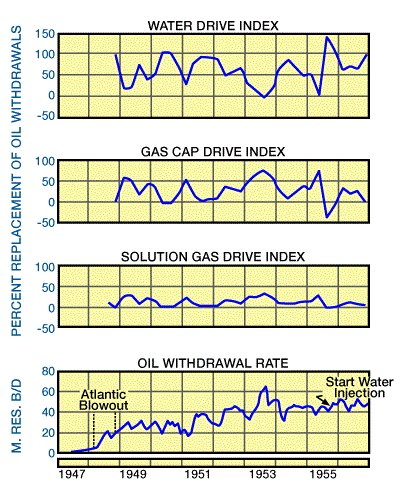
To 1954, the water drive had contributed 50%, the gas cap had contributed 40%, and solution gas drive had contributed 10% to the replacement of reservoir oil.
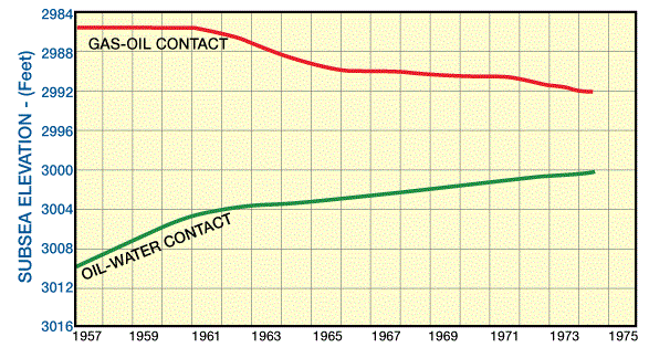
New discoveries (other adjacent fields) during 1952-53, which were proven to have a common aquifer with D-3 pool, had caused an interference. During this period, pressure decline in Leduc D-3 amounted to 100 psi (68.95 kPa). In order to prevent this undesirable pressure decline and to avoid shrinkage losses in the Leduc D-3 reservoir, water-injection operations started in 1955. A volume of 18.5 million barrels (2.94 million ![]() ) of fresh water was injected up to 1957, which arrested the pressure decline and increasing GOR. It was estimated that up to 1957 water injection could prevent the loss of one million barrels of oil which would have occurred by shrinkage of the reservoir oil under natural depletion. As a result of the water injection, the descent of the gas-oil contact was de creased and the ascent of water-oil contact was increased. By the end of 1957, with a cumulative oil production of 90 million barrels (14.3 million
) of fresh water was injected up to 1957, which arrested the pressure decline and increasing GOR. It was estimated that up to 1957 water injection could prevent the loss of one million barrels of oil which would have occurred by shrinkage of the reservoir oil under natural depletion. As a result of the water injection, the descent of the gas-oil contact was de creased and the ascent of water-oil contact was increased. By the end of 1957, with a cumulative oil production of 90 million barrels (14.3 million ![]() ), the effective thickness of pay zone was reduced to approximately 23 ft (7.015 m) which is an indication of the excellent production that was characteristic of the Leduc D-3 pool. This was due to the very high permeability of the reservoir and the large ratio of the horizontal to vertical permeability. Pool performance is shown in Figure 2 and Figure 3.
), the effective thickness of pay zone was reduced to approximately 23 ft (7.015 m) which is an indication of the excellent production that was characteristic of the Leduc D-3 pool. This was due to the very high permeability of the reservoir and the large ratio of the horizontal to vertical permeability. Pool performance is shown in Figure 2 and Figure 3.
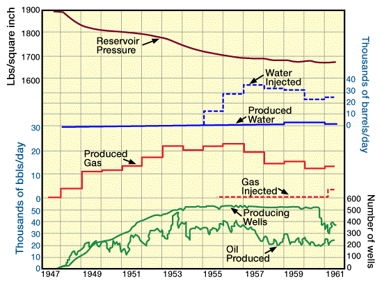
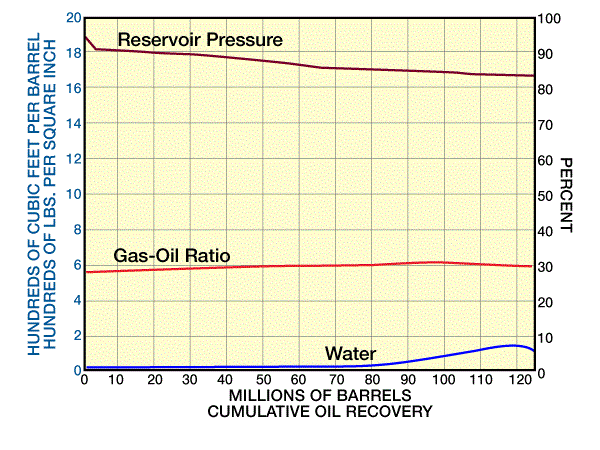
Detailed studies were made on natural depletion, continued water injection, and pressure maintenance by both water and gas injection. It was concluded that for maximum recovery, the water and gas injection operation together should be considered. For implementation of this new injection scheme, a unitization of 456 wells in the main pool was accomplished in 1960 and was followed by gas injection in 1961. By 1974, a production recovery of 70% or more of the initial oil in place was accomplished. The gas-oil contact showed again the steady rise of water-oil contact and lowering of gas-oil contact. The bottomhole pressure never dropped below 1350 psi (9.3 MPa). The aim was to keep the gas-oil contact at 2992 ft (912 m) sub-sea, allowing the water-oil contact to move upward to replace oil voidage. By the end of 1974, when only 8 ft (2.44 m) of pay zone was left (Figure 4), the average GOR was 2000 ![]() (356
(356 ![]() ) and water-oil ratio was 0.5.
) and water-oil ratio was 0.5.
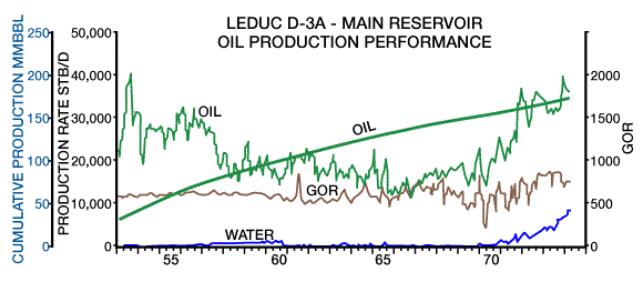
The absence of oil and water coning throughout most of the pool’s history confirms that a high ratio of horizontal to vertical permeability existed throughout the oil zone. This characteristic allows the pool to be maintained for a very thin oil zone and is perhaps the most significant factor contributing to the outstanding performance of this pool under combination drive. The reservoir performance of Leduc D-3 till 1975 is shown in Figure 5.
Exercise 01:
What quantities define the state of gases?
Solution
Pressure, volume, and temperature are the quantities used to define the state of gases.
Exercise 02:
What is the equation of state for an ideal gas?
Solution
The equation of state for an ideal gas is
![]()
Exercise 03:
How does water influx affect the p/z versus GP plot?
Solution
Water influx invalidates the straight line relationship of Gp versus p/z. Thus, such a plot cannot be used (in instances where water influx is an important factor).
Exercise 04:
Which is the most efficient recovery mechanism for a gas reservoir? Why?
Solution
Expansion is the most efficient recovery mechanism for a gas reservoir because water traps gas that is lost to recovery.
Exercise 05:
Why is it important to maintain the reservoir pressure of gas condensate reservoirs above the dewpoint?
Solution
We maintain reservoir pressure of gas condensate reservoirs above the dewpoint because the liquid that condenses is practically lost, since most, if not all of it, constitutes the critical saturation, and hence does not flow.
Exercise 06:
Describe how the performance of condensate reservoirs is predicted.
Solution
The best way to predict condensate reservoir performance is from laboratory depletion data. The depletion or exploitation scheme planned for the reservoir is simulated experimentally in a high-pressure cell. Recovery of increments of gas and distillates as a function of pressure is then determined experimentally.
Exercise 07:
How is pressure maintained in condensate reservoirs? What is meant by gas cycling?
Solution
Pressure is maintained in condensate reservoirs by injecting gas, or water, or both. When the distillates are stripped off, the produced gas and the dry gas is returned to the reservoir. This operation is called gas cycling.
Exercise 08:
What is the advantage and disadvantage of maintaining the pressure by water drive or injection?Solutionclick to hide solution
The advantage of water is that it may result in higher E1. Its disadvantage is that it results in a considerably lower ED.
Exercise 09:
Define abnormally pressured reservoirs.
Solution
Abnormally pressured gas reservoirs are those whose average fluid pressure gradient is substantially higher than 0.433 psi/ft.
Exercise 10:
When, in an abnormally pressured gas reservoir, can you use the p/z versus Gp plot to calculate the initial gas in place and cumulative production versus pressure?
Solution
You use the p/z versus Gp plot to calculate initial gas in place and cumulative production versus pressure only if the second straight line segment is adequately defined. This segment may then be extrapolated to obtain Gp versus p/z.
Exercise 11:
Define solution gas drive reservoirs. What are the phases of production that may occur in such reservoirs?
Solution
Solution gas drive reservoirs are those in which the principal mechanism of production is the expansion of the oil, the gas dissolved in the oil, and the rock with its associated water. Two phases of production may occur-he undersaturated phase (when the pressure is above the bubble-point pressure) and the saturated phase (when the pressure falls below the bubble-point pressure).
Exercise 12:
How does ultimate recovery vary with the cumulative gas produced for solution gas reservoirs?
Solution
Ultimate recovery varies because the more gas that remains in the reservoir, the higher the ultimate recovery. Thus, ultimate recovery decreases with increase in cumulative gas production.
Exercise 13:
State the three main phases of the GOR behavior for a solution gas drive reservoir.
Solution
The three main phases of GOR behavior are:
- A constant GOR when the pressure is above pb
- A sharp rise in GOR as a free gas phase develops and flows
- A decline in GOR as the reservoir pressure declines to abandonment pressure
Exercise 14:
What are the principal advantages of initiating pressure maintenance by water injection when the pressure is at or close to pb (i.e., no free gas is present)?
Solution
There are two principal advantages of water injection when pressure is at or close to pb:
- with no free gas, the relative permeability to oil for a given oil saturation is higher. Thus production is higher for a given drawdown;
- the volume of water required to maintain an oil production rate is lower.
Exercise 15:
What recovery factor should one expect from a solution drive mechanism?
Solution
The recovery factor of a solution drive mechanism very seldom exceeds 30%, and is normally around 15%.
Exercise 16:
What is the effect of a gas cap on reservoir pressure, recovery, and GOR?
Solution
With a gas cap, the reservoir pressure and recovery will be higher compared to strictly solution gas drive values. The produced GOR is lower in early production life and much higher in late production life.
Exercise 17:
What corrective measure should the engineer undertake if gas from the gas cap breaks into a well?
Solution
If gas from the gas cap breaks into a well, work over and recomplete the well at a lower interval. If this is not possible, the well should be shut in to prevent unnecessary depletion of the reservoir energy.
Exercise 18:
Water influx, We, is a function of what variables?
Solution
We is a function of time and pressure. It is an unsteady-state process.
Exercise 19:
What remedial action should the engineer undertake when water breaks through into a well?
Solution
If the reservoir is fairly homogeneous, water will break through, due to gravity at the bottom part of the sand. In this case, the well should be recompleted at a higher location. In case of heterogeneous reservoirs, water may break through in the most permeable layer first. This layer should be squeeze-cemented to minimize the problems of water handling.
Exercise 20:
Can one use the MBE to determine N, m, and We? If not, how are the three unknowns handled?
Solution
The MBE cannot be used to solve simultaneously for the three unknowns. Normally m is estimated volumetrically, and N and We are solved by using Havlena and Odeh’s (1963) method.
Exercise 21:
Enumerate the factors favorable to gravity drainage and state how each factor affects gravity drainage.
Solution
The favorable factors for gravity drainage are:
- The amount of difference in density between oil and gas—the higher this figure is, the stronger will be the effect of gravity drainage.
- The higher the vertical ko and kg, the stronger gravity drainage is.
- Low viscosity of oil favors gravity drainage.
- A high angle of dip favors gravity drainage.
- A large cross-sectional area between the segregated gas and the oil zone results in a higher rate of oil segregation.
Exercise 22:
What is the upper limit of the recovery factor under gravity drainage?
Solution
The upper limit of recovery under gravity drainage is equal to ![]()
Exercise 23:
What is a drive index and what is its significance?
Solution
A drive index is the percent or fractional contribution of a drive mechanism to total production. It indicates the relative strength of the drive mechanism.
Exercise 24:
What are the modern tools for predicting the performance of a reservoir producing under combination drive?
Solution
Reservoir simulators are used to predict performance of reservoirs producing under combination drive.
Assessment
1. Select the true statement(s) of which given below.
A .Perfect gas law assumes that the kinetic motion of gas molecules are stronger than the electrical attractive forces
B .Continuing to produce watered-out wells remobilizes trapped gas
C .Heterogeneity and stratification can result in prematurely watered-out producing wells
D .A and B
E .B and C
F .All of the above ✔
2. Which of the following statements is FALSE?
A .The composition of a gas condensate lies between that of a volatile oil and a dry gas
B .Typically, distillate API gravity is less than 30 API ✔
C .A liquid phase develops as pressure decreases below the dew point
D .B and C
E .A and B
F .A and C
3. Recovery from cycling operations in gas condensate reservoirs depends on:
A .The areal sweep
B .The vertical sweep
C .The microscopic displacement
D .A and C
E .All of the above ✔
4. The principal drive mechanism(s) of a solution gas drive reservoir is:
A .The change in in-situ stresses
B .The expansion of the rock with associated water
C .The expansion of the gas dissolved in the oil
D .A and B
E .B and C ✔
5. Which of the following statements is TRUE?
A .Pressure maintenance by water injection is utilized to enhance ultimate recovery ✔
B .Below the bubble-point gas/oil ratio is constant
C .As pressure decreases below the bubble-point, the free gas phase disappears
D .A and B
E .All of the above
6. Which of the following methods is NOT used to predict the performance of solution gas reservoirs?
A .Muskat method
B .Gringarten method ✔
C .Tracy method
D .Tarner method
7. Recovery of the gas cap reservoirs is affected by:
A .The locations of wells
B .The degree of the heterogeneity of the reservoir
C .The size of the gas cap
D .A and B
E .All of the above ✔
8. Material balance applications of gas cap reservoirs assume:
A .The rock and water compressibilities are insignificant
B .Strong water influx
C .The gas in gas cap is compressible
D .A and C ✔
E .All of the above
9. What is NOT necessary to know, in determining cumulative water influx?
A .Initial pressure
B .Volume of the water in the aquifer
C .Reservoir permeability ✔
D .Water and rock compressibilities
10. Water cut is defined as:
A .The water breakthrough in production wells
B .The molbility ratio when it is equal to 1.0
C .The water free production
D .The percent water in total fluid production ✔
11. Water influx is NOT a function of:
A .The depth of the aquifer ✔
B .The porosity of the aquifer
C .Pressure drop
D .Time
12. Which of the following statements is TRUE about gravity drainage mechanism?
A .It is time dependent ✔
B .It is most effective in thin reservoirs with shale stringers
C .The rate of segregation is a function of porosity and absolute permeability
D .It is a quite fast process
13. The material balance application for combination drive reservoirs does NOT include:
A .The oil expansion
B .The gravity segregation ✔
C .The expansion of the rock
D .The water influx
 Petro Shine The Place for Oil and Gas Professionals.
