Related Articles


Production logging is a technique used to evaluate the performance of a well by measuring the flow rates and properties of different fluids produced from the well. When it comes to multiphase flow in horizontal wells, production logging becomes more complex, but it remains an important tool for optimizing production and identifying issues in the well. Multiphase flow in horizontal wells occurs when two or more fluids, such as oil, gas, and water, flow together in the same wellbore. Production logging in such situations typically involves measuring the flow rates, phase fractions, and other parameters of each fluid using specialized tools.
Introduction
Welcome to this topic on Production Logging of Multiphase Flow in Horizontal Wells.
In this topic, we will describe :
- Differences between multiphase flow in horizontal and vertical wells.
- Special techniques devised to obtain logs and high angle wells
- Logging suites designed to measure multiphase flow in horizontal wells.
Multiphase flow behaves quite differently in vertical well bores than in horizontal, near horizontal and undulating well bores. To characterize flow in horizontal wells, it is necessary to understand such factors as:
- The effect that wellbore deviation has on flow regimes,
- The types of flow regimes that exist in horizontal wells
- The capabilities and limitations of tools and methods used to obtain flow data in horizontal wells.
By taking these factors into consideration, you should be able to :
- Select the appropriate measurement technology to characterize the flow conditions in your well.
- And gain a better understanding of the limitations which may affect your interpretation of horizontal flow data.
Configurations and Flow Regimes
The advent of horizontal drilling brought new and unexpected challenges with respect to characterizing flow regimes in horizontal wells. New approaches to logging, fluid flow interpretation and evaluation, and wellbore configuration were developed in response to those challenges.
One obvious problem presented by the horizontal wellbore was that wireline tools could no longer be pulled to total depth by gravity. As borehole inclination approaches sixty degrees (60) from vertical, friction increases to the point that wireline tools cannot freely fall to the bottom of the well. In this horizontal environment, gravity is no help at all. This unit will discuss some of the methods that were devised to overcome this problem.
As with vertical wells, it was necessary to identify commercially productive perforations, as well as to determine which intervals produced water. However, the results obtained by conventional production logging tools were generally not sufficient to characterize horizontal flow regimes. These conventional tools were designed to measure vertical flows, in which fluid phases are dispersed with near uniformity across the wellbore. With few exceptions, conventional production logging tools were not capable of characterizing horizontal flow in any detail. This experience prompted the study of horizontal flows in order to develop logging tools capable of discerning each phase within the flow.
The problems encountered in horizontal wells were not merely related to flow patterns and downhole tool designs. The broad application of slotted liners, gravel packs, and external casing packers pose problems in understanding and characterizing flow in horizontal wells.
Through such configurations, fluids can move both within the casing or liner, and through the annulus. As a result, the point at which a logging tool detects a sudden inflow into the borehole may not, in fact, mark the actual source of the fluid entry.
This unit focuses on current methods of measuring multiphase flow in horizontal wells. Though current technology has not addressed all of the problems associated with horizontal production logging, oil companies and logging companies continue to study the nature of multiphase flow downhole, and seek to develop more accurate tools to characterize flow in horizontal wells.
Horizontal Well Configurations
The term “horizontal well” is very loosely used in the industry, since no well is ever completely horizontal, except over the course of short intervals. In this discussion, the term “horizontal well” will encompass any well that is horizontal (90 degrees of deviation), near-horizontal (within 10 degrees of horizontal), or undulating (deviation fluctuates above and below 90 degrees). The important factor to recognize is that in a “horizontal well” a change of only a few degrees in inclination (e.g. changing from 88 to 90 or 92 degrees from vertical) can make a dramatic difference from a production logging perspective. The angle affects which fluid phase (heavy or light) will be dominant within the cross section of the wellbore. A slight change in well angle can dramatically affect individual phase velocities.
To visualize this situation, consider the examples shown in Figure 1 (Horizontal well configurations; after Smollen, 1996).
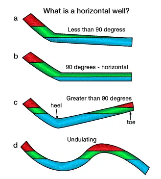
Imagine a shut-in well, in which the fluids have segregated so that both the gas-oil interface and the oil-water interface are present. Well fluids segregate according to density where the deviation angle is less than 90 degrees, as illustrated in part a of Figure 1. Water is shown at the bottom of the well, above which are oil and gas respectively. If the well is truly horizontal, multiple phases may be present along the horizontal section (see part b of Figure 1) and no particular phase will necessarily dominate. While only water and oil are present in the horizontal section shown in part b of Figure 1, clearly all three phases could be present, given sufficient volumes of water, oil, and gas. If the well angle is greater than 90 degrees, as shown in part c of Figure 1, then the water will accumulate at the lowest point, or heel, of the well. Moving away from the heel in either direction would first involve crossing a water-oil interface, then later crossing an oil-gas interface. Unlike the earlier example, the end of the horizontal section of the well is filled with gas.
In actuality, no wells are completely horizontal for any lengthy extent; instead, they are generally greater or less than 90 degrees, or may even “undulate” as shown in part d of Figure 1. This example illustrates a shut-in well in which the phases have segregated in a more complex manner. The light phase, shown as gas, accumulates at the crest of the undulation, while water accumulates at the trough. The oil phase, if present, would accumulate between the water and gas phases. The ramification of this fluid segregation within a supposedly “horizontal” well is that segregation continues even during flowing conditions, unless flow velocities are extremely high.
Fluid identification logging tools are sometimes used to determine which fluid phases are present within the wellbore, and to measure each fraction at any point along the wellbore. Under ideal conditions, if such a tool provided excellent and reliable information within the horizontal environment, then the character of the logs would be much more affected by the well inclination than the entry profile. In vertical wellbores, the fluid identification tool provides an important indicator of fluid entry, but in horizontal wells, these indications could be misleading in the absence of other amplifying information; especially the directional survey.
Horizontal Well Completions
A variety of completion methods may be employed in horizontal wells. Figure 2 – Types of Completions; Smollen, (1996), shows some of the most typical configurations.
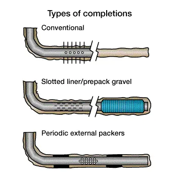
Each type of completion poses a different problem for the production logging tool.
The term “conventional” completion is used to describe a cemented and perforated cased hole completion, as well as an open-hole completion, as shown in the upper part of Figure 2. These two completions are classified as conventional because, in both cases, all of the flow is confined to the segment of borehole through which the logging tool passes (assuming that a good cement bond in the cased hole was established). In the cased hole, however, fluid must enter through the perforations (assuming good casing integrity), while in the open hole, fluid may enter from anywhere. Furthermore, the segment of open hole may be rugose and is likely to accumulate more debris along the well than a cased completion.
Other wells fall outside the realm of conventional completions. The slotted liner and pre-packed gravel pack completions are shown in the middle part of Figure 2. These completions are both characterized by an open annulus along which fluid can flow. As a result, any inflow detected at the liner or gravel pack screen is not necessarily representative of the actual source of the flow from the formation. The fluid may enter the annulus at one point, flow along the horizontal section, and suddenly be diverted into the liner or screen by a restriction or closure along the annulus. Such restriction or closure can occur, for example, when the formation collapses or swells. Production logging tools designed for conventional wells may not be effective in this situation, and may provide misleading measurements.
A periodic external casing packer completion is shown in the lower part of Figure 2. This completion is much like the slotted liner completion, and would appear to have the same problems. It does, however, provide features that are more conducive to effective production logging. This method typically uses a number of packers in the completion, so fluid entries to the casing are confined to those sections that are open to the annulus. This completion may exhibit flow characteristics similar to a “conventional” horizontal completion when measured adjacent to the packers because the flow is restricted to the same section of borehole that the logging tool occupies. When flow is measured between entry points in the casing and adjacent to packer sections, the flow contributed from each interval between packers can be determined without needing to account for flow in the annulus. If logging tools that are affected by annular flows are used to make measurements between packers, the log will resemble that seen in a slotted liner completion.
Flows In Horizontal And Near-Horizontal Wells
Flows within “conventional” completions are the most easily measured of horizontal flows. If the flow comprises only a single phase, then the response of most production logging tools (with the exception of the gradiomanometer or other pressure differential density tool) is essentially the same as that seen in a vertical well. If more than one phase is present, however, the flow segregates into a pattern as shown for two phases in Figure 3 – Flow patterns in a conventional completion; Smolen (1996).
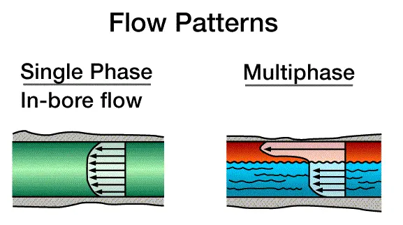
While any of these patterns is possible, the stratified flow regime is most likely to be encountered under producing conditions. In this flow regime, the water, oil, and gas phases are segregated by density, with oil on top of water, and gas on top of oil. The lighter phases generally move faster in an upward direction than the heavier phases. Minor changes in well deviation are capable of causing large changes in fluid velocity and holdup. Variations in fluid and gas velocity tend to generate different flow patterns which can complicate the log interpretation. Generally, stratified flow will dominate in horizontal wells unless flow rates are quite high. This is also the type of flow that the newer production logging equipment has been designed to measure.
The flow pattern map of Figure 4 – Flow regimes in the horizontal environment; Smolen,(1996), shows the nature of flow expected for two-phase gas/liquid flow under specified conditions.
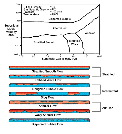
The superficial velocities for a phase, Vs , is defined as the volumetric flow rate of that phase divided by the cross section area of the pipe:

where:
Vs= superficial phase velocity
Q= bulk flow rate of the phase
A= cross-sectional area of the pipe
To put this equation into perspective, for 7 5/8 inch, 29.7 lb/ft casing, a flow rate of 1000 B/D corresponds to a velocity of 15.1 tf/min . or .25 tf/s . Below a superficial liquid velocity of 10 tf/min, and for the conditions stated in Figure 4 , the flow will be either stratified or intermittent (essentially broken stratified flow). Dispersed bubble flow will not be produced until the liquid flow rate reaches nearly 40,000 barrels per day! Indeed, below a liquid flow of about 1000 barrels per day, the flow is almost always stratified over a very wide range of gas flows, given the conditions stated.
Non-conventional horizontal completions, such as slotted liner completions, exhibit flow properties that are much more difficult to evaluate. Figure 5 – Concurrent flows in liner, prepacked gravel packs, and external packer completions; Smolen (1996) shows the types of flows encountered.
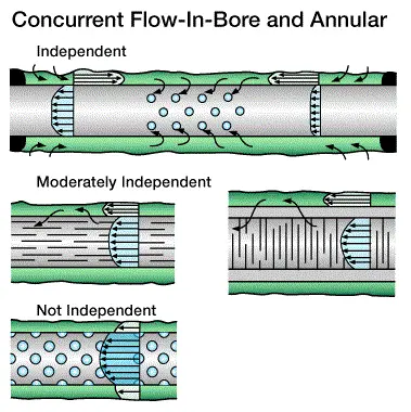
Generally, there will be concurrent flows in both the liner and the annulus. These flows may exhibit varying degrees of independence relative to one another. Such independence implies that a measurement of flow in one region will not provide any information about flow in the other region. Any tools designed to measure concurrent flows must be able to discriminate the flow phase and its velocity – both inside and outside of the liner. Though nuclear tools currently provide the best capability to characterize flow within the annular region, the goal of obtaining concurrent flow measurements with any degree of confidence and consistency is yet to be fully realized.
