Related Articles


Production Logging Tools Designed for Horizontal Wells
A number of new production logging tools have been developed specifically for horizontal wells. Each service company has its own unique approach to evaluating horizontal multiphase flow; there are no generic measurements within this class of new tools. Some of the sensors described can be used in vertical or deviated holes, as well as in horizontal wells.
Most toolstrings employ a combination of conventional production logging sensors and special sensors designed for horizontal wells. This combination provides data redundancy and cross-referencing for assessing the quality of the interpretation. As well deviations vary, some sensors will work more effectively in one part of the wellbore than they will in another part of the well. When different sensors point to the same conclusion, they bolster the strength of the interpretation. When there is disparity between sensors, then the engineer can decide which sensor should be expected to provide the most reliable reading for any particular interval.
This discussion focuses on the approaches adopted by some of the leading innovators in petroleum technology, though other tools and technologies may have been developed by any of a wide number of smaller logging companies. To date, three of the leading service companies have directed their efforts toward measuring multiphase flow rates in horizontal wells having either conventional open hole or cased, cemented, and perforated completions. In this rapidly changing technology, new sensors are currently being developed by each of the major service companies.
Schlumberger tools
The first tool string designed to log horizontal flow was the Schlumberger PLF lagship TM Production Logging Tool String. The tool was introduced in 1996 following collaboration between British Petroleum and Schlumberger to develop technology particularly suited for the horizontal well environment. This collaboration produced innovations that are featured in the Schlumberger PS Platform TM, a new-generation production logging system which provides improved measurements through collocation of critical sensors. The tools are shown schematically in Figure 1 – Schlumberger Flagship production logging toolstring.
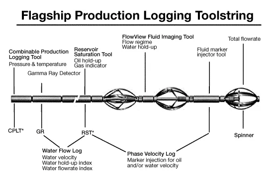
New measurements featured on the PL Flagship string include the PVL TM Phase Velocity Log using the RST TM Reservoir Saturation Tool and the FloView Plus TM cross-sectional fluid hold-up imager. The RST is also used to generate the WFL TM Water Flow Log using the tool’s oxygen activation capability. Conventional sensors for flow evaluation include a full-bore flowmeter and a conventional pressure and temperature sonde. The response of the full-bore flowmeter and the temperature recorder is discussed under the heading entitled Conventional Production Logging Tools.
The RST is a pulsed-neutron tool capable of making both sigma and carbon/oxygen measurements. It is set up much like a conventional capture tool with both near and far gamma ray detectors. There is also a third gamma ray detector located further downstream on the tool, with spacing between the three detectors set to obtain the optimal measure of water flow velocity.
The Water Flow Log (WFL) is based on the activated oxygen technique. A 14 MeV neutron burst activates the oxygen in water molecules as they flow past the tool’s neutron generator. Gamma rays are given off by the activated oxygen as it returns to the steady state. The gamma rays and travel time are measured as the water flows the known distance between the neutron generator and the gamma ray detector. This technique is used only for water velocity, and is not able to provide oil velocity measurements.
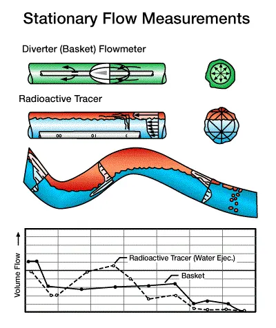
The Phase Velocity Log (PVL), measures the separate velocities of the oil phase and the water phase. The measurements depend on a technique borrowed from radioactive tracer velocity logging, discussed in the section entitled Stationary Flow Measurements (see Figure 2 – Stationary flow measurements in horizontal wells).
The fluid marker ejector section (labeled E on the schematic) contains both water and oil tracer fluids. The fluids are laced with a soluble gadolinium compound that has a high capture cross-section, but which is not radioactive. When a tracer fluid is ejected, the tracer fluid seeks its phase, travels with that phase, and is detected as it passes the RST. The RST detects the tracer fluid by monitoring the borehole capture cross section after the tracer is ejected. The RST measures the time of travel from the ejector to the RST.
If L is the distance between the ejector and the RST and t is the time of travel between those points, then the velocity of that phase is simply:

The FloView tool, shown in Figure 3 – FloView schematic, is used to determine phase holdup.
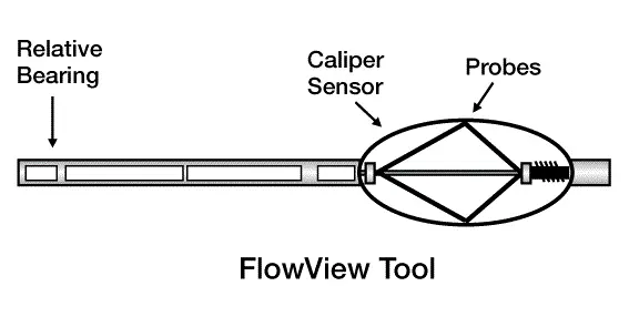
The tool utilizes four centralizer arms; each with a tiny resistance probe positioned a short distance from the wall. In the vertical or moderately deviated environment, these probes detect bubbles and then average the resistivity readings from the four probes to calculate a holdup value. High and low resistivity values measured across a threshold band allow the tool to discriminate between water and hydrocarbon phases. Water holdup is calculated from the span of time during which the voltage measurement falls within a particular voltage threshold. Bubble count is determined from the number of voltage oscillations across the threshold. Water holdup and bubble counts are independently mapped from each probe.
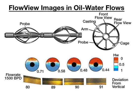
To effectively log within the horizontal environment, two sets of centralizer arms (eight probes) are run in tandem, with one sonde rotated 45 degrees relative to the other. When run in this dual mode, the service is called FloView Plus. This configuration assures that a resistivity probe is positioned at 45-degree increments around the wellbore, providing eight independent, local holdups and bubble counts.
A relative bearing measurement tracks tool rotation and the positions of each probe relative to the high and low sides of the hole. This information is used to generate an oriented map of fluid segregation. In the horizontal environment, this dual sonde arrangement provides information on the water/hydrocarbon interface in stratified flow, as shown on Figure 4 – FloView Plus detects oil-water interface. The probes can also detect intermittent hydrocarbon/water flows.
The holdup measurement is not affected by jet effect, friction, or extreme water cut values. Note that the tool cannot discriminate between oil and gas.
If only two phases are present downhole, there will be sufficient information to determine the volumetric flow rates of each of the two phases. Once the phase velocities and holdups are known, then the volumetric flow rates of each phase, is given by the equation:

where:
Q= the volumetric flow rate,
V= the phase velocity,
A= the cross section of the pipe,
Y= the holdup, and
C= flow profile correction factor.
When three phases are present, the RST may be used as a three-phase holdup tool. The three-phase measurement is quite difficult and complex. Essentially, the RST emits neutrons from an electronically activated source. These neutrons interact with nuclei in the formation, which then give off gamma rays as the excited nuclei return to their original state. The gamma rays are counted by the near detector (spaced one foot from the neutron source), and the far detector (spaced two feet from the source). The gamma ray spectra measured by each detector is used to determine the carbon/oxygen ratio. This measurement is affected by the oil and water in the borehole, as well as by the formation itself. The near/far (N/F) count ratio is particularly sensitive to gas. The C/O measurements are used to determine the holdups of water, and oil, while the N/F ratio is used for gas holdups, assuming that the formation characteristics are known.
A brief review of tool functions is shown below:
- Full Bore Spinner Measures velocity, but is marginally useful.
- Phase Velocity Log Measures the velocity of the water phase and the oil phase.
- FloView Plus Locates the hydrocarbon/water interface or water holdup.
- WFL Measures water velocity.
Though capable of obtaining three-phase holdups, the Flagship is not capable of determining the velocity of the gas phase. Schlumberger is developing new production logging sensors to provide more direct measurements of those properties currently determined by calculation. In particular, the PS Platform is expected to evolve with the addition of new sensors to become easily configurable for all flow regime scenarios.
Halliburton tools
The Halliburton tool configuration is shown in Figure 5 – Halliburton production logging tool configuration.
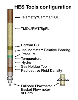
The main new production log sensors include the Gas Holdup Tool TM (GHT TM), and the Spectral Flow Log TM (SpFL TM), which will be discussed in more detail below. Other tools featured in this toolstring include:
- Gamma Ray and Casing Collar Locator: provide correlation with other logs.
- Temperature Tool: identifies temperature changes which may indicate intervals of fluid entry or escape.
- Pressure Tool: for analyzing pressure drawdown or buildup.
- Fluid Density Tool: uses gamma ray absorption to measure density of the borehole fluid.
- Hydro Tool: uses dielectric measurements to distinguish water from hydrocarbons.
The GHT is shown schematically in Figure 6 – Gas Holdup Tool for vertical and horizontal flow.
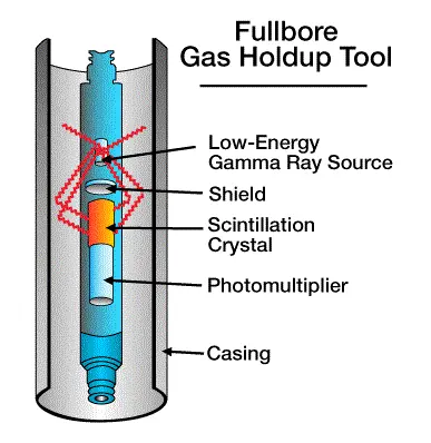
Unlike center-sample tools, the GHT makes fullbore measurements which are not affected by the tool’s centralized position within the flowing stream. Centralization enables the tool to work at any angle of wellbore inclination – including horizontal.
The GHT uses a low-energy gamma ray source and relies on a combination of Compton scattering and photoelectric absorption of gamma ray energy to determine fluid holdup. A low-energy source emits gamma rays that are not capable of penetrating the casing, therefore, the measurement are not influenced by conditions outside the casing. Unlike the nuclear fluid density measurements, in which a decrease in counts implies a greater fluid density, the count rate increases with density when the back-scatter gamma rays are counted. The relationship between count rates and gas holdup depends on the casing size and the liquid component of the fluid, but is nearly linear.
After the gamma rays lose energy through Compton scattering, photoelectric absorption of gamma ray energy can take place. Because oil and water exhibit offsetting photoelectric and Compton sensitivities, very little difference in count rate is seen between either phase. Therefore, the gas holdup measurement is almost totally independent of the mixture or salinity or the oil and water phases.
Wellbore deviation will not affect the measurement of the gas holdup. When three phases are present, it measures the gas and liquid holdups. If no gas is present, the GHT is capable of discriminating oil holdup from water holdup.
The SpFL is actually a pulsed neutron tool that has been adapted for oxygen activation water flow measurements. This tool has the unique capability to determine an index related to the distance between gamma rays given off by activated oxygen and the detector. This index can be used to discriminate water flow inside the casing from that occurring outside the casing.
With the GHT and other conventional holdup sensors, the Halliburton tool string can be used to determine the holdup of each of the three phases. If the Reservoir Monitoring Tool (RMT) is on the tool string, it can be used to determine the carbon/oxygen ratio of borehole fluids and hence discriminate the oil and water phase fractions within the liquid phase holdup. The use of the diverter basket flowmeter coupled with the oxygen activation water flow measurement provides good answers in two-phase flow, but will not resolve volumetric flow rates of gas and oil in three-phase flow.
