Related Articles


Single-Stage Cementing Process
When the casing is in place and conditioned mud has circulated long enough to remove any gelled mud from the annulus, circulation must be stopped long enough to load both cement plugs into the cementing head.
Generally, one of the following sequences are followed:
- Drop bottom plug, pump spacer, pump cement, drop top plug, displace cement with mud, or
- Pump wash, drop bottom plug, pump spacer, pump cement, drop top plug, displace cement with mud, or
- Pump wash, drop bottom plug, pump cement, drop top plug, displace cement with mud
A two-plug primary cementing operation is illustrated in Animation 1.
As a general practice, the bottom wiper plug should be placed between the fluids of highest density difference, as long as a sacrificial volume is tolerated for the contamination between the other fluid interfaces (such as spacer and cement). To avoid contamination of the cement by the mud-contaminated spacer in situations where that could lead to retarded development of compressive strength, the bottom plug may be dropped within the last portion of the spacer in a sequence:
- Pump wash
- Pump nearly all of spacer
- Drop bottom plug
- Pump last portion sacrificial volume of spacer
- Pump cement slurry
- Drop top plug
- Displace cement with mud
Dropping the wiper plugs should not take longer than the time needed to open and close the valves at the cement head. Cementing heads and top drive cementing equipment have wireless tools for remotely executing these operations with minimal time loss. If pumping is stopped for more than five minutes, downhole fluids could develop gel strength. This could require additional pressure to restart fluid movement, a situation that could in extreme cases lead to formation fracturing downhole, or the creation of pockets of gelled mud that could inhibit uniform cement placement.
A bottom plug is not recommended for use with cement slurry containing large amounts of lost-circulation material or with casing that is badly rusted or scaled internally. Such debris may collect on the edges of the ruptured diaphragm of the bottom plug, bridge off the casing, and prevent total displacement of the slurry, jeopardizing the success of the job.
Because of U-tubing, the top of the cement inside the casing may actually be a considerable distance below the top wiper plug when it is dropped. Depending on the cement volume and density, the cement may already have rounded the casing shoe when the plug is dropped. The rate at which the cement is displaced into the annulus is not necessarily the same as the rate of pumping into the casing head. Once U-tubing has ceased and continuous flow is restored into the casing and out of the annulus at the surface, displacement continues until the top wiper plug is “bumped.”
The pump rate is usually reduced near the end of the displacement to avoid a sharp pressure increase when the plug reaches the collar. Upon bumping the plug, if pressure holds, the casing can be pressure tested (provided that the plugs and collar have been selected to permit this test without breaking).
Surface pressure is then released and the casing is observed for back flow that would indicate the float equipment is not functioning properly. If no back flow is observed, the line is left open during the waiting-on-cement (WOC) time period. This is the time allotted for the cement to set and develop sufficient compressive strength.
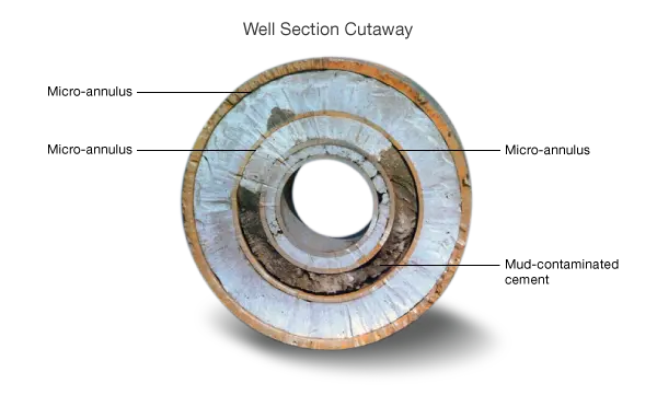
If the float collar does not hold, the mud returns must be pumped back into the casing, maintaining pressure on the casing until the cement sets. However, it is important to bleed off any excess casing pressure that develops (due to thermal expansion of the cement in the annulus). If this is not done a micro-annulus may form between the casing and cement sheath because of expansion and contraction of the casing (Figure 1).
When the cement has started to set, the normal practice of landing the casing in the wellhead can be performed. The casing will be hanging from the rig elevators and after the cement has set, the BOPs are lifted from the casing head and suspended from the substructure. Slips and the casing pack-off assembly are then set between the casing and casing head. A new casing head is then flanged to the previous one and the BOPs are attached before the next section of hole is drilled.
