Related Articles


Slurry Design Considerations
Slurry design is an iterative process. A formulation that is expected to meet the required performance criteria is created based on experience and local or regional databases. Laboratory testing is performed to verify predicted results and refine the design. Testing of the final design with field samples is essential to ensure that the slurry to be pumped is consistent with the slurry designed in the lab.
One of the most important considerations in cement slurry design is density. Slurry density is dictated by:
- Fracture gradient
- Expected pore pressures
- API class of cement chosen
- Overall well objectives including economics
In the past, higher density cement slurries were created to develop rapid compressive strength. Today however, high compressive strength cements can be designed at very low densities through the careful control of cement particle sizes.
Each well offers a range of acceptable hydrostatic pressures. A worst-case scenario involves identifying the zone of highest pore-pressure and the zone of lowest fracturing pressure (Figure 1).

Normally, the weakest zones in a well are exposed to the highest pressure immediately before the completion of the job (before the top plug lands). At this point, the longest column of slurry will be in the annulus and friction pressure will be at its highest level. This is generally considered to be the time with the highest likelihood of a formation breakdown.
Conversely, the worst-case scenario from a well control standpoint occurs when the fluid of lowest density in a cementing program (typically a chemical wash pumped ahead of the cement) passes a zone with high pore pressure.
In the absence of any other considerations, the maximum allowable downhole density possible without causing fracturing should be chosen for the cement slurry – at least 1  , preferably 2 or 3 , heavier than the drilling mud.
Pumping excess cement to ensure adequate annular fill is a common practice when the borehole size is uncertain due to washouts. However, if the borehole is closer to gauge than expected, this excess can cause cement to be circulated to a higher point in the annulus than planned for, and if weak zones are present the higher hydrostatic pressure can lead to a fracture, loss of cement, and potential loss of the well. Similarly, if a low density wash or spacer is pumped to a higher than expected point in the annulus, the resulting drop in hydrostatic pressure can lead to influx and loss of well control.
Slurry Design Example
A North Sea well was drilled out of the surface casing prior to cementing the 9-5/8 inch intermediate casing at a depth of 6,476 ft (1,974 m). The well was nearly vertical, and nearly in gauge with an open-hole diameter ranging from 12.2 to 13 inches (31 to 33 cm), although a few washed out sections between 900 m and 1,175 m depth in the Barremian formation enlarged the hole to up to 18 inches (46 cm) as shown in Figure 2.

The Albian formation is a high pore pressure water zone that must be properly isolated, but weak formations below the Albian prevent the use of normal density cement slurry. There are salt/evaporite formations along the open hole section. A very good bond across the casing shoe is critical because the mud weight must be increased from 9.8 to 17.1 for drilling the lower 8-1/8 inch hole out of the 9-5/8 inch casing.
One option would be to perform the cement job in two stages, allowing for placement of high density slurry across the Albian aquifer zone. This would be expensive, however, requiring significantly more rig time and the potential need for remedial cementing. The decision was made to perform a single stage cement job using lightweight lead slurry and a short, normal density tail slurry to provide high strength at the casing shoe.
The known geothermal gradient of  (
( ) was used to calculate a static temperature at the shoe of 176 °F (80 °C). The bottom hole circulating temperature (BHCT) calculated from API tables is 123 °F(50 °C). Circulating the conditioned drilling mud at a density of 9.8 (1,150
  ) at a rate of 6.3
  for about 2.5 hours lowered the annular temperature at the shoe to the BHCT. A computer simulation showed that the annular temperature profile after this circulation was about 50 +/- 2 °C from about 750 m to the casing shoe (Figure 3). The temperature near the Albian aquifer of concern was approximately at the geothermal gradient of about 47-48 °C.

The portion of the cement slurry pumped first, the lighter-weight lead slurry, is a 11.5 density slurry with the following additives:
- Dispersant to facilitate mixing of a high-solids slurry
- Fluid loss additives to avoid bridging off across the permeable zones
- Salt (18% by weight of water) to help alleviate problems in the evaporate intervals
- Retarder to achieve a thickening time of 7-8 hours. The job is expected to take 4 to 5 hours to complete, so with a 50% safety margin, the minimum thickening time should be 6 to 8 hours
The tail slurry, pumped second, is designed to be heavier with a density of 15.9 , the same dispersant, fluid loss additives, salt, and a retarder that provides for slightly less thickening time than the lead slurry (about 5 to 6 hours).
Because the annulus (9-5/8 inch OD casing in a 12 to 13 inch hole) had a relatively small clearance, achieving turbulent flow could result in high effective circulating density (ECD) and risk breaking down weak formations. The best option for ensuring good mud removal was determined to be a combination of spacers and chemical washes. A computer simulation program was used to calculate optimal slurry rheology.
The fluid volumes, properties and job schedule are shown in Table 1.
| Fluid Pumped or Activity | Vol. (Bbl) | Annular distance (ft) | Density (lbmgal) | Rate (bblmin) | Stage Time (min) | Elapsed Time (min) | Cum. Vol. (bbl) |
|---|---|---|---|---|---|---|---|
| Start Job | |||||||
| Chemical Wash | 26.8 | 9.6 | 4.0 | 6.6 | 6.6 | 26.8 | |
| Spacer | 119.9 | 11.0 | 8.0 | 15 | 21.6 | 146.8 | |
| Drop bottom plug | 5 | 26.6 | 146.8 | ||||
| Lead slurry | 522.5 | 5,869 | 11.5 | 5.3 | 98.2 | 124.8 | 669.2 |
| Tail Slurry | 53.7 | 607 | 15.9 | 6.7 | 8 | 132.8 | 722.9 |
| Drop top plug | 5 | 137.8 | 722.9 | ||||
| Mud | 400.0 | 9.8 | 8.0 | 50 | 187.8 | 1122.9 | |
| Mud | 93.1 | 9.8 | 5.3 | 17.5 | 205.3 | 1216.0 | |
| Mud | 66.3 | 9.8 | 4.0 | 16.6 | 221.9 | 1282.3 | |
| Mud | 55.4 | 9.8 | 2.7 | 20.7 | 242.6 | 1337.6 | |
| End Job |
The job began with pumping a 27-barrel chemical wash at 4 barrels per minute followed by a 120 bbl high viscosity spacer at a rate of 8 bbl per minute, the highest pump rate that would be reached during the job.
Next, the bottom plug was dropped, followed by the lead slurry, which was planned to rise all the way to the surface in the annulus. After the entire job was pumped, the tail slurry was calculated to extend 607 feet above the casing shoe in the annulus, while the lead slurry would extend from the top of the tail slurry to the surface, another 5,869 feet. The lead slurry was pumped at a rate of 5.3 while the tail slurry was pumped a bit faster at a rate of 6.7 . Total cement pumping time was just under two hours.
The top plug was dropped behind the tail slurry, followed by a 9.8 mud was used to displace the cement to bottom. The mud was pumped at rates that decreased in stages, beginning at 8 and ending at 2.7 , to ensure that the plug was bumped safely. The overall job time was about 4 hours.
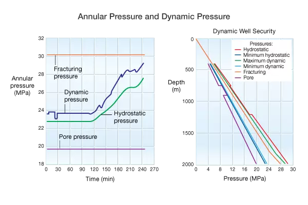
A simulator was used to assess annular pressures at the casing shoe over time and dynamic frictional pressure relative to fracturing pressure along the entire borehole (Figure 4). The minimum and maximum pressures were within the limits of pore pressure and fracturing pressure, ensuring a successful job.