Related Articles


Casing Program Overview
Casing programs are an integral element of the well planning and design process. In general, casing programs reflect a “bottom-up” or “inside-out” design process. For example:
- The design process starts with the innermost tubulars: the tubing string and accompanying downhole production or injection equipment, which is designed for the anticipated formation pressures and production or injection rates.
- Moving outward, the production casing or liner is designed to accommodate the tubing string(s).
- Continuing outward, the design moves progressively toward the surface, with the intermediate, surface, and conductor casing.
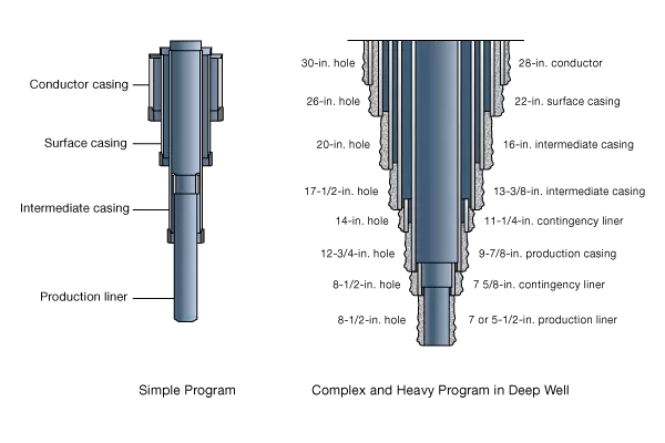
Figure 1 illustrates a relatively simple casing program as described above, along with a complex program that involves setting multiple contingency and intermediate strings.
Casing Specifications and Performance Properties
Casing is specified in terms of:
- Length
- Outside diameter and wall thickness, which determine the casing’s inside diameter and weight per unit length
- Grade, which indicates the tensile strength and minimum yield stress of the material, and is based on the chemical composition of the steel and the heat treatment methods applied
- Connections, which refer to the type of thread or coupling used to join individual lengths of casing
The length, diameter, and wall thickness define both the volume of the casing and the volume of the annulus between the casing and borehole or between concentric casing strings. These volumes determine how much cement slurry, spacer, wash fluid, or displacement fluid are needed for a particular job.
Casing specifications result in a casing string exhibiting certain mechanical properties:
- Burst strength: The minimum internal pressure that will cause the casing to rupture in the absence of external pressure and axial loading
- Collapse resistance: The minimum external pressure that will cause the casing to rupture in the absence of internal pressure and axial loading
- Tensile strength:
- Pipe body: The tensile force that will cause the casing to exceed its elastic limit
- Joint strength: The tensile force that will cause failure in the casing connection
It is important to consider the load conditions that cementing operations might place on casing, and to determine whether these loads could exceed the casing strength.
| Casing Type | Purpose |
|---|---|
| Conductor | Protects very shallow formations from drilling fluids Prevents erosion or caving of surface sediments or the sea bed below the rig Enables fluid returns to the flow line or mud line Provides support for subsequent casing stings |
| Surface | Seals off problem formations found at relatively shallow depths Isolates fresh water formations and prevents their contamination by drilling fluid or fluids from deeper formations Is the first casing string employed to control subsurface pressures Permits the safe drilling of shallow gas zones below the casing shoe |
| Intermediate | Protects shallow formations from the high mud gradients Allows changes in mud type Seals off problem formations |
| Production | Maintains wellbore integrity and pressure control in the pay zone Isolates zones through selective perforation Conducts formation fluid to wellbore Protects well and subsurface environment in case of tubing failure Facilitates repair or replacement of production equipment |
Conductor Casing
The conductor is the shallowest string of casing, (Figure 2) and the first one set in the well. Setting depths can be as shallow as 20 ft and is usually less than 300 ft. Outside pipe diameters can range from 18 to 42 inches, with 30 inches being a common size.
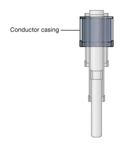
The hole for the conductor can be drilled or the conductor can be jetted into position or driven into the sediment using a pile driver. When the conductor hole is drilled or jetted, the pipe can be cemented into place by pumping cement and observing cement returns at the surface. In cases where the pipe is driven into the ground, it may be left uncemented.
Functions
Conductor casing serves the following purposes:
- Protect very shallow formations from drilling fluids.
- Prevent erosion or caving of surface sediments or the sea bed below the rig.
- Enable fluid returns to the flow line or mud line.
- Provide support for subsequent casing stings for the diverter system used before installation of a blowout preventer (BOP) stack.
Cementing Considerations for Conductor Casings
Conventional Onshore Wells
Typical slurries for conductor casing applications at conventional onshore wells include API Class A, C, G, or H with 2% calcium chloride as an accelerator. Lost-circulation additives such as sand, gilsonite, and cellophane may be added without significant effect on the slurry-thickening time or compressive strength. Where lost circulation is severe, a thixotropic cement can be used. When the cement cannot be circulated back to surface, a “top-out” slurry may be pumped into the annulus from the surface through small tubing (this is called “grouting”) on top of the primary cement.
Offshore Deepwater Wells
Installing a conductor at offshore locations in deep water can be complicated by abnormally high saltwater flow formations, and the existence of weak formations that can fracture and cause loss of cement returns.
A typical arrangement would be to drive a 30-inch OD pipe to 200 feet below the mud line and then cement a 20-inch OD conductor string by pumping cement through the drill pipe until cement returns back to the ocean floor via the annulus.
However, at deepwater locations low subsea temperatures slow the cement hydration process, which allows water or gas influx from shallow formations to form channels that destroy cement sheath integrity (Griffith, 1995). Successful techniques for deepwater conductor cementing include:
- Circulating a good mud that contains fluid loss control additives and exhibits low gel-strength development as the conductor hole is drilled and before running casing
- Using a high-viscosity spacer
- Incorporating rigid centralizers on the conductor
- Using nitrogen-foamed cement with accelerators to reduce hydrostatic pressure on weak formations and hasten the onset of hydration in the 40 to 60°F temperatures prevalent in the deep US Gulf waters
- Using ultrafine/hollow ceramic bead slurries that are lightweight, but also high-compressive strength
Surface Casing
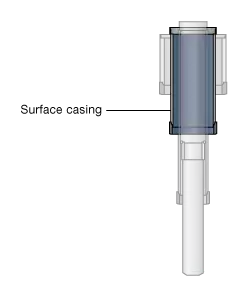
The surface casing is run after the conductor pipe (Figure 3), and cemented at depths ranging from a few hundred to a few thousand feet. The actual setting depth depends on the proposed total well depth, the competency of the shallow formations encountered during drilling, and state regulations regarding protection of freshwater zones. Surface casing diameters can vary from 7 inches to 26 inches.
Functions
Surface casing serves the following purposes:
- Seals off problem formations found at relatively shallow depths, such as lost circulation zones, unconsolidated formations, heaving or sloughing shales
- Isolates fresh water formations and prevents their contamination by drilling fluid or fluids from deeper formations
- Is the first casing string employed to control subsurface pressures, and must be strong enough to support a BOP stack and provide a solid anchor for a casing head to hang off subsequent casing strings
- Permits the safe drilling of shallow gas zones below the casing shoe
Cementing Considerations for Surface Casings
A common problem with cementing surface casing is placing the required height of cement in the annulus (often to the surface) when the hydrostatic pressure of the slurry exceeds the fracture pressure of formations within the surface hole. Low-density slurries and foamed cement are options for solving this problem.
Operators who are cementing surface casing strings also must contend with borehole washouts in unconsolidated intervals. This leads to uncertainty in determining the actual hole volume and the need to design significant excesses into the planned slurry volumes. An open hole caliper log measures hole diameter, and can be useful in reducing this uncertainty.
Intermediate Casing
One or more intermediate casing strings (sometimes referred to as “protection” strings) may be required below the surface casing (Figure 4). Setting depths can vary from 1000 to more than 17,000 feet, with outside diameters ranging from 6-5/8 inches to 16 inches.
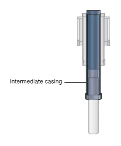
Intermediate casing is usually run to the surface and, like the surface casing, anchors and connects the BOP stack with a higher pressure rating for subsequent drilling operations. However, in certain deep wells intermediate “contingency” liners may be run. Often the intermediate string requires the largest volume of cement of any string in a well and is also the string through which the longest period of drilling time occurs.
Functions
Intermediate casing serves the following purposes:
- Protects shallow formations from the high mud gradients needed in deeper intervals (while allowing for mud weight reduction in case of pressure regression in deeper formations)
- Allows changes in mud type
- Seals off problem formations such as hydrocarbon-bearing, abnormally pressured zones, fractured formations, low pressure gradient formations, expanding shale, salt, or anhydrite during the drilling process
One or several intermediate strings may be necessary to maintain borehole integrity at greater drilling depths and to separate the hole into workable increments for drilling.
Cementing Considerations for Intermediate Casings
Unlike conductor and surface casings, additives such as friction reducers, fluid-loss additives, and retarders are more commonly required for intermediate slurries. Where the annulus is small, friction reducers allow lower pump pressures and reduce the chance of losing fluids in a lost-circulation zone. Fluid-loss additives prevent slurry loss into lost-circulation zones and dehydration in the annulus caused by permeable zones, and also improve bonding results.
High-performance, lightweight cements permit intermediate strings to be cemented in a single stage, although multistage cementing may be necessary if even this approach fails to accommodate weak formations or if it is imperative that a specific hydrocarbon-bearing layer be well isolated. Multistage cementing is more common in intermediate strings than other casing strings.
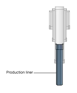
Production Casing
Production casing or liner strings are the final “layer” of protective tubular elements making up a well Figure 5. Production tubing, through which hydrocarbon fluids flow, is installed inside the production casing. In rare cases flow is through the production casing itself. Typical production casing OD sizes are 4-1/2to 9-5/8 inches. Setting depths can vary from 1500 feet or less to more than 25,000 feet.
Functions
Production casing serves the following purposes:
- Maintains wellbore integrity and pressure control in the pay zone.
- Isolates zones through selective perforation.
- Conducts formation fluid to wellbore.
- Protects well and subsurface environment in case of tubing failure.
- Facilitates repair or replacement of production equipment.
A production liner performs these same functions without the expense of running casing all the way back to surface.
Cementing Considerations for Production Casing
Production casing is normally run and cemented through the zone to be produced and then perforated to permit communication from the reservoir to the wellbore. The slurry used to cement production casing must be designed to keep the producing zone under control during the cementing process while minimizing filtrate loss to the formation that could reduce permeability. Fluid loss rates should be kept less than  , preferably in the
  range and even less in the case of high-pressure, high-temperature wells.
The general guideline for adequate zonal isolation by the cement across the producing formation is 1,000 psi compressive strength and less than 0.1 millidarcies of water permeability. When bottomhole temperatures exceed 230 °F, compressive strength can be maintained by adding 30% to 40% by weight silica flour to the dry cement.
Combination Strings
In certain cases it may be advantageous to vary the casing size within a single string of casing, with a smaller diameter casing on the bottom connected by a crossover swage to a larger diameter casing on the top. This configuration, also known as a tapered string, may be used when there are wider diameter tubing components higher in the well (such as gas lift mandrels, a subsurface safety valve, or multiple tubing strings for a multiple zone completion).
