Related Articles


Core Porosity Analysis Techniques
Techniques for analyzing core porosity include:
- Boyle’s Law
- Summation of Fluids
- Resaturation
Boyle’s Law Technique
The Boyle’s Law technique for measuring a formation rock’s porosity is a gas transfer method that involves the compression of gas into the pores, or the expansion of gas from the pores, of a clean, dry rock sample. The bulk volume, grain volume and the pore volume may be determined, depending upon the instrumentation and specific procedures used. It is an accurate technique when performed carefully, and is a fairly rapid process for the majority of typical core samples. It also leaves core material that can be used for further testing. It is essential that the samples be clean and dry, otherwise erroneously low porosity values will be generated.
Bulk Volume
The measurement of bulk volume is critical when the pore volume is being calculated from the difference between the bulk volume and grain volume. A good technique uses Archimedes’ principle of displacement. One of two methods can be used. The first method requires that the sample be saturated with a liquid and then weighed. The sample is then submerged in the same fluid, and its submerged weight taken. The bulk volume is the difference between the two weights divided by the density of the fluid with which the core is saturated and in which it is immersed.
The second method also requires that the sample be saturated with a suitable liquid. Fresh water is typically used because it can be easily vaporized from the core after the test has finished. After saturation, the sample is immersed in a small vessel of water previously placed on laboratory scales. For this immersion, the core sample must be suspended and lowered into the water without touching the sides of the vessel. Two weights are taken: that of the vessel and water before the core sample is immersed; and that of the vessel, water and sample afterwards. The weight difference is equal to the weight of the water displaced by the core sample. Because the density of fresh water is 1.0 g/cm3, this weight difference in grams is numerically equal to the bulk volume of the core sample in cubic centimeters.
The bulk volume can also be determined by calipering the length and diameter of a core sample and then applying appropriate mathematical formulae. Generally, the information obtained by calipering is not sufficiently accurate to derive valid porosities when grain volume is to be subtracted to derive the pore volume. In other cases, the bulk volume is determined by a direct measure of the pore volume, and this is summed with a direct measure of the grain volume.
Grain Volume
Measurement of the grain volume is easily completed using a Boyle’s Law porosimeter illustrated in Figure 1.
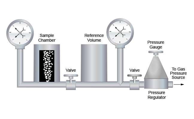
A clean, dry sample is placed in a chamber of known volume. This chamber is isolated from the upstream pressure chamber, which is also of known volume. The upstream pressure chamber is charged to a pressure of approximately 100 psi (689 kPa) and then isolated. The connection between the pressure chamber and sample chamber is opened and gas expands into the sample chamber, causing a drop in the original reference pressure. If the volumes of the pressure and sample chamber are known, the grain volume may then be calculated by using the measured pressures and the following equation:


where:
 = Reference cell volume
 = Sample cell volume
 = Grain volume of sample
 = Initial presure in refence cell
 = Final pressure in system
In rocks containing free carbon and clays, air molecules can be adsorbed on the mineral surfaces and thus produce an erroneous measurement of grain volume and porosity. This limitation is overcome by the common procedure of using helium gas in the laboratory apparatus. Helium gas has an extremely small molecule that rapidly penetrates small pores. It is inert and will not be adsorbed on the rock surfaces, as air can sometimes be. The helium porosimeter uses the principle of gas expansion, as described by Boyle’s Law. A known volume (reference cell volume) of helium gas, at a predetermined pressure, is isothermally expanded into a sample chamber. After expansion, the resultant equilibrium pressure is measured. This pressure results from the volume of the sample chamber minus the rock grain volume and, therefore, the porosity can be calculated.
Experiments conducted by Kazimierz et al. (2004), and others, have established that helium porosimeters provide repeatability of measurements, high precision and small random error on the obtained results:
“The following can be assessed for the helium porosimetry method with reference to the measured porosity values in the fulfilled repeatability conditions:
- Standard deviation (absolute value) St Dev. ≈ 0.07%,
- Variability coefficient (relative standard deviation) 0073,0ˆ ≈ v (i.e. 0.73%).”
These results establish that when used appropriately, helium porosimeters are highly precise devices in the repeatability conditions, with a low value of random error of the measurement results.
Another advantage of this method is that the grain volume determined using this measurement can be subsequently combined with the measured weights of the sample to generate reliable grain density values. Such data is important for deriving log porosity from density LWD and wireline logging tools. Note that incomplete cleaning and insufficient drying will lead to erroneously low grain densities and erroneously high grain volumes.
Pore Volume
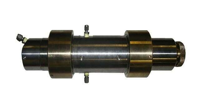
Pore volume is often determined indirectly by calculating the difference between measured values of bulk volume and grain volume. It can also be measured directly by using Boyle’s Law equations. To do this, it is necessary to alter the sample holder from the configuration illustrated in Figure 1. The sample must be placed in a holder that has no void space around the periphery of the core and on the ends. An apparatus suitable for this measurement is referred to as a Hassler holder (core holders that have radial pressure applied to the core sample) or a hydrostatic load cell. The hydrostatic load cell is illustrated in Figure 2, and shown pictorially in Figure 3.
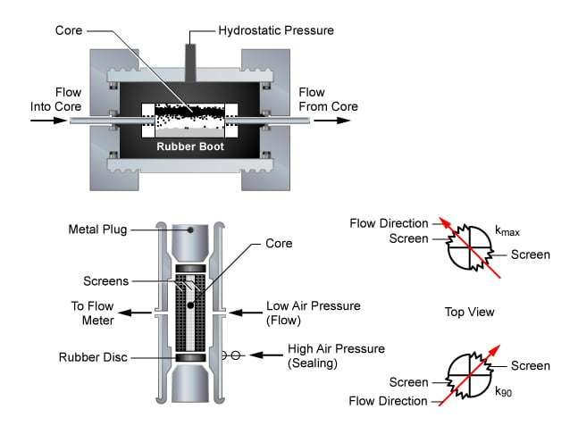
Helium can be injected into the core through the end stems as illustrated in Figure 2, and the sample’s pore space established. Dead volume in the system is measured by substituting a solid metal plug for the core plug. The sample is then inserted. It is essential that the end stems butt closely up against the sample faces. If not, a dead volume not measured with the metal plug is created, which will generate an erroneously high porosity reading. The sample should have flat end surfaces at right angles to the axis of the core. The fact that some samples are less than perfect can be compensated for by placing a thin rubber pad (with a central hole) between the sample face and the metal end stem. The compressible rubber fills the space and allows the calculation of valid data.
Measurements on those cores that are not clean and dry generate values of pore space that are too small. Table 1 presents selected data measured on core samples that were rushed through the core analysis without adequate time for core drying. These particular data were required within a short time frame for well completion purposes and while adequate for that objective, would not be suitable for estimating resources and reserves.
| Parameter | Inadequate drying* | Properly dried |
|---|---|---|
| Porosity | 6.7 | 7.8 (+16.4 %) |
| Grain density | 2.62 | 2.64 (+.02 g/cm3) |
| Permeability | 0.03 | 0.06 (+50 %) |
Table 1: Impact of Inadequate Drying on Porosity, Grain Density, and Permeability Measurements
In summary, Boyle’s Law porosity is a very accurate method, which is not sensitive to the rock’s mineralogy. Although cleaning and drying of the core sample is required, it remains a quick technique. Porosity can be determined at the reservoir stress conditions and permeability can be measured on the same apparatus, which avoids stress hysteresis effects. The rock’s grain density is readily determined and the core samples can be reused for additional testing. The technique can accommodate irregularly shaped, fractured and vuggy samples.
Summation-of-Fluids Technique
Porosity determination of core samples by the summation-of-fluids technique has been used extensively for many years. The technique measures the gas, oil and water in the pore space of fresh core samples of known bulk volume. The oil and water volumes are determined through retorting to the samples at high temperatures. The gas volume is determined by direct mercury injection. These volumes are summed to establish the pore volume and, hence, the porosity. This is a rapid analytical technique which assumes that the total volume of the oil, water and gas in a material constitutes the pore volume of that material. When it is used with the proper oil and water calibrations, it generates valid porosity values. The technique is well suited for routine laboratory work, and it allows both porosity and saturations to be determined on the same sample.
The summation-of-fluids technique requires measurements on two portions of a core. One portion is approximately 100 g in weight and is crushed into fragments approximately 1/4 inch (0.6 cm) in diameter. These are placed in a cylindrical metal holder with a cap on one end (Figure 4). Extending from the opposite end of the holder is a long, steel condensing tube, approximately 1/4 inch (0.6 cm) in diameter.
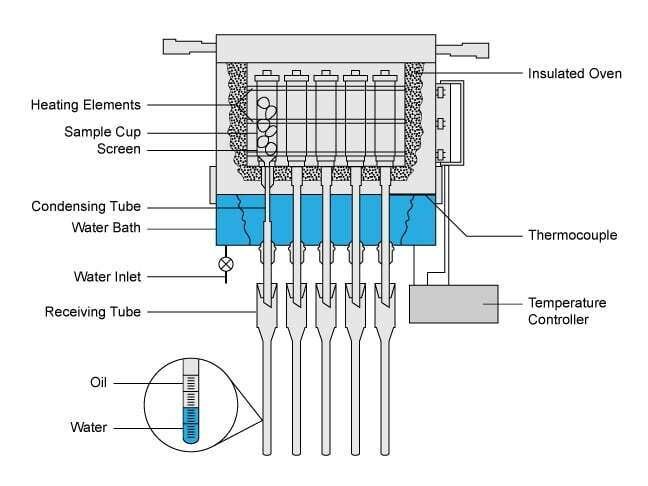
Each sample holder contains material from a single sampled depth, and multiple sample holders are placed in a retort and heated simultaneously. The water and oil contained within the pores are vaporized, move down through the stainless steel tube and are subsequently condensed into calibrated glassware. The volumes of oil and water are read and recorded for future calculations. A second portion of rock weighing approximately 30 g is obtained by shaping a piece of core to a roughly cylindrical form. The sample is weighed and its bulk volume is determined by mercury displacement. The sample is then immersed in mercury, and pressure on the mercury is raised to approximately 1000 psi (6895 kPa). At this pressure, mercury enters the sample and compresses the gas, filling the unoccupied pore space. This establishes gas volume as a percentage of bulk volume of the sample.
Knowledge of the bulk volume and weight of the fresh sample into which the mercury is injected allows the computation of the natural density of the rock. This in turn is used to convert the 100 g to be retorted into an equivalent bulk volume. The oil, water and gas volumes are each reported as a fraction of the bulk volume of the rock from which they came, and the three values are summed to generate the porosity.
This is not a suitable technique for those core samples that have been exposed to the atmosphere and from which residual oil and water could have evaporated. Fresh cores contain residual oil and water in the finer pore spaces, and any injected mercury only fills the larger spaces occupied by gas. In cores in which all liquids have evaporated, the mercury will not penetrate the smaller, gas-filled pores at the 1000 psi (6895 kPa) pressure imposed, and the resulting porosity value will be erroneously low.
Oil Volume Determination
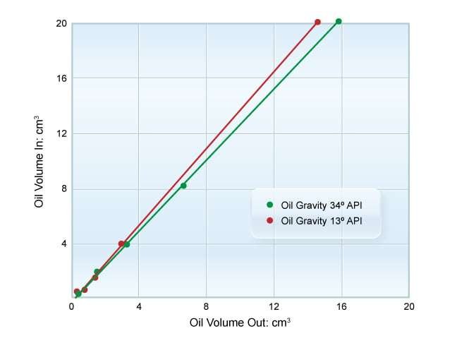
The oil and water contents of a sample are determined by high temperature retorting at temperatures of up to 1200º F (650º C). Some oil is lost within the system because of the coking and cracking of oil contained within the pore space. This results in an observed oil volume in the condensing glassware that is less than that actually present in the core. A correction is made to increase the observed oil volume prior to the calculation of a summation-of-fluids porosity. This correction is based on calibration curves that had been made previously using oils similar to those from the area from which the core was recovered. In those cases where no oil is available, a standard correction has generally proved adequate. The correction curve is only slightly affected by the API gravity, primarily because of the high temperatures induced during the analysis. A typical oil correction curve is shown in Figure 5.
Water Volume Determination
During retorting, the recovered water volumes are read at a point that distinguishes pore water from the mineral water of crystallization. A plot of water recovered from individual cores as a function of time is shown in Figure 6. These are cumulative water-recovered curves, and most are distinguished by a plateau that represents water held within the pore space by capillary forces.
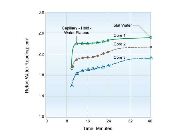
This is the water that is required in the summation-of-fluids analysis. A second plateau representing a greater water volume is termed “total water” in the analysis, and this represents the pore water plus any water that has been contributed by adsorbed water or water molecules within clays. Pore water can generally be easily distinguished from the mineral water of crystallization if no clays or other hydratable minerals are present. When clays are present, it is likely that some water of crystallization will be included in the summation, and the computed porosity and water saturation values will therefore be higher than actual. This error will be proportional to the percentage of clay present in cores.
Various researchers have documented that data can be improved if the water value were read after subjecting the cores to a temperature of 350° F (177° C) for a minimum of 30 minutes. This effectively extends the plateau, and improves the differentiation between the capillary-held water and that formed by the breakdown of minerals present.
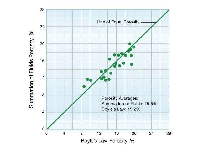
Figure 7 shows a comparison of the summation-of-fluids porosity using water read at 350° F (177° C) versus the Boyle’s Law porosity using helium.
Porosity
The summation-of-fluids technique can be approximately verified using a balance to derive the grain density as illustrated in the following equations:


and

where:
 = rock grain density,
 = oil density,
 = water density, (assumed 1.00 for water collected)
 = weight of crushed rock in retort less weight of contained fluids, g
 = weight of crushed rock in retort, g
 = grain volume,
 = volume of oil collected, (corrected for vapor losses, coking, etc.)
 = volume of water collected,
 = volume of unoccupied pore space, corrected based on retort sample weight,
 = bulk volume of sample used to determine unoccupied pore space, corrected based on retort sample weight,
Further verification is supplied by a comparison of the summation-of-fluids porosities with a porosity value calculated through a Boyle’s Law procedure on adjacent plugs. This comparison requires that the plug used for Boyle’s Law porosity analysis be properly dried. Excessive drying will dehydrate clays and generate an erroneously high helium porosity that may agree with the erroneous summation-of-fluids porosity data. When hydratable clays are encountered, combination analysis techniques using (1) oil and gas volumes developed from summation-of-fluids and (2) porosity from helium injection on a properly prepared core together will establish the water saturation by difference calculations. Table 2 presents data generated on a shaly sandstone and illustrates the potential errors in porosity that are possible if rocks are improperly analyzed. The example quoted is an actual case, but the magnitude of porosity differences shown here is unusually high. These rocks contained up to 30% montmorillonite, an amount not normally observed.
| Table 2: A Comparison of the Results of “Combination Analysis” and “Summation-of-Fluids” Techniques on Cores Containing Hydratable Clays | |||||||
|---|---|---|---|---|---|---|---|
| Saturations, % Pore Space, Combination Analysis* | Saturations, % Pore Space, Summation of Fluids Analysis** | ||||||
| Porosity | Oil | Water | Gas | Porosity1 | Oil2 | Water3 | Gas4 |
|
* Correct technique ** Technique was unsuitable for this rock which contained hydratable clays 1 Helium porosity on properly cleaned and humidity dried core at 145° F and 45% humidity 2 Oil volume from summation-of-fluids divided by helium pore volume 3 Helium porosity (1) minus summation-of-fluids gas and oil as a percentage of bulk volume 4 Gas volume from summation-of-fluids mercury injection divided by helium pore volume | |||||||
| 34.0 | 45.8 | 33.8 | 20.4 | 43.4 | 34.2 | 48.4 | 17.4 |
| 36.4 | 47.3 | 30.2 | 22.5 | 44.1 | 39.2 | 42.4 | 18.4 |
| 28.2 | 53.5 | 27.7 | 18.8 | 35.8 | 42.3 | 43.1 | 14.6 |
| 34.9 | 51.0 | 28.7 | 20.3 | 40.3 | 44.2 | 38.2 | 17.6 |
| 37.9 | 60.2 | 25.3 | 14.5 | 47.9 | 47.7 | 40.9 | 11.4 |
Analysis of fractured shales containing gas or oil poses special problems. The retort temperature reached in the summation-of-fluids analysis technique is sufficiently high to break down kerogen materials, whose presence is indicated by dark oil recovery in the retort tube. If cores are selected from a known dry gas or condensate zone, the contribution of the kerogen material may be easily determined. If the matrix and/or fractures contain a dark oil, temperature control and a combination analysis with another technique is required, so that only the live oil is removed and no contribution from the kerogen is included. Oil from the kerogen material would not be recovered under conventional production practices and inclusion of this material in the calculations will generate an erroneously high porosity in the laboratory analysis.
When a conventional core is analyzed, it is important that attention is paid to securing adjacent portions of rock to use for gas and liquid saturation determinations. Heterogeneous cores can have widely varying pore geometry in adjacent samples and thus yield erroneous porosity values. Plug samples are normally not used for heterogeneous rock, but, when necessary, this sampling problem can often be overcome with careful attention to the sample selection.
Drilling mud flushing of the core can create another problem (Figure 8). If the sample used for gas measurement is taken from the inner portion of the core and the samples for liquid saturations are taken from the more highly flushed outer portion, the calculated porosity will be higher than the true value. Again, this can normally be overcome with proper sample selection procedures, but should be recognized as a potential source of error.

Sidewall Core Analysis
Most percussion sidewall cores are analyzed for porosity using the summation-of-fluids technique. Mercury is first injected into the core sample to establish the gas space. The same sample is then retorted to establish the oil and water saturations, using procedures previously described. Rotary sidewall cores generate more reliable porosity data, not being subjected to the alteration effects of the percussion sidewall core acquisition process.
In summary, the advantages of the summation-of-fluids method are:
- It is a rapid technique which requires no cleaning or drying of the core samples.
- It is reasonably accurate for most rock types.
- Porosity and saturation can be determined on sample splits.
Resaturation Technique
The resaturation technique for porosity determination requires that the core samples be cleaned and dried prior to measurement. A dry weight of the core is taken and the sample is then evacuated and pressure saturated with either water or a light hydrocarbon. The difference between the saturated and dry weights establishes the grams of fluid within the pore spaces. Dividing this value by the density of the saturating fluid generates the pore volume. The procedure is slow, fairly difficult to conduct and requires that the fluids used to saturate the rock wet, but do not react with, the rock surfaces. Incomplete resaturation will cause erroneously low porosity values. An advantage of this method is the possibility of using the samples for further testing, although the core must be re-cleaned if oil is used to saturate the rock. When done properly, the technique is accurate; however, the results are sensitive to the sample preparation. The samples must be clean and dry prior to the initial weighing, otherwise an erroneously low porosity will be measured.
The resaturation method is commonly used as a quality control check in special core analysis tests, as many measurements require resaturation of the core samples. Comparison of the resaturation-measured porosity with an originally measured Boyle’s Law porosity value for the same sample pinpoints problem areas when the results from the two methods do not agree.
In summary, porosity determination by the resaturation technique is accurate, but slow—the saturation time is highly dependent on the permeability, and the saturated samples are available for further testing.
