Related Articles


Learning Objectives
After completing this topic “Permeability Measurement“, you will be able to:
- Discuss the laboratory methods used to measure permeability.
- Describe permeameter measurements of formation permeability.
- Summarize the factors affecting a rock’s measured permeability values.
- State the accuracy of laboratory permeability measurements.
Introduction to Formation Permeability and its Measurement in the Laboratory
Permeability is the measurement of a rock’s ability to transmit fluids a critical property of reservoir rocks (Figure 1).
The primary permeability unit is the “Darcy,” after the French engineer Henry Darcy who first described the flow of water through sand filters. One Darcy is defined as that permeability which permits a fluid of one centipoise viscosity to flow at a rate of one cubic centimeter per second through a porous medium with a cross-sectional area of one square centimeter under a pressure gradient of one atmosphere per centimeter. In SI units, a permeability of one meter squared will permit a flow of 1  of fluid of 1 Pa viscosity through an area of 1 m2 under a pressure gradient of 1
  .
.
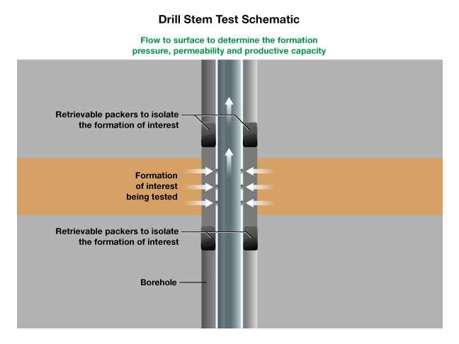
Permeability can either be determined from the analysis of core samples in the laboratory, or through well tests such as drill stem tests (Figure 2). A drill stem test (DST) is a procedure for isolating and testing the pressure, permeability and productive capacity of a geological formation in situ within a reservoir formation while drilling a well.
Permeability of Conventional and Unconventional Reservoirs
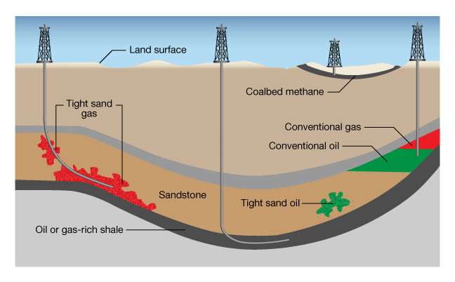
Conventional gas, occurring in discrete accumulations related to localized structural features and/or stratigraphic conditions, typically with each accumulation bounded by a down-dip contact with an aquifer (Figure 3), is often found to be commercially exploitable in reservoirs, if they are of sufficient volume for their specific location, with permeabilities greater than 0.1 millidarcy (mD), and can be extracted using traditional development and production techniques.
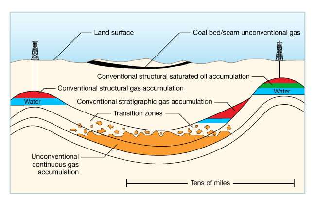
A large proportion of the hydrocarbon gases which have been produced globally to date have been conventional resources. In reservoirs of moderate to good permeability, conventional gas is often relatively easy to extract, especially when compared to the recovery of hydrocarbons from unconventional resource reservoirs.
By contrast, unconventional gas accumulations are pervasive throughout a large area and are not significantly affected by hydrodynamic influences. Tight gas and shale gas are found in formations with very low permeabilities. Shale gas reservoirs have extremely low permeability, often in the range of 1 to 1,000 nanodarcies (10-9 darcy), and the gas cannot normally be extracted through conventional production methods, but rather require both horizontal development wells and hydraulic fracture stimulation (fracking) (Figure 4). Hydraulic fracture stimulation is a process through which a large number of fractures are created mechanically in the reservoir rock, allowing the natural gas and/or crude oil trapped in very low permeability subsurface formations to move through those fractures to the wellbore from where it can then flow up to the surface. Fracking can increase both the production rates and the total amount of gas that can be recovered from a given volume of shale. Liquid hydrocarbons normally require higher permeabilities than gas for the same reservoir conditions in order to attain economic viability.
Measurement of Permeability
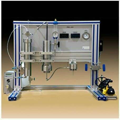
In the laboratory, air or a gas is flowed through a clean and dry core sample of measured length and diameter (Figure 5). Dry gas has traditionally been used as the standard fluid for use in laboratory permeability determinations, primarily because it is inexpensive, minimizes the fluid-rock reactions and is easy to use. The pressure differential and flow rates are measured, and the permeability is calculated using Darcy’s equation.
At high pressures, the Darcy equation for compressible fluids (gases) can be represented by the same equation as incompressible fluids. However, at low pressure, flow of gases (compressible) is quite different than flow of liquids (incompressible) – flow rate is proportional to the difference of the squares of pressure rather than the pressure difference driving flow.
This conversion of a volume at atmospheric pressure to the volume existing at mean pressure is accomplished using the following equations:
Incompressible Fluid Flow (Liquid)

Compressible Fluid Flow (Gas)

Where:
 = liquid flow rate,
 = gas flow rate at atmospheric pressure, cm2s
 = viscosity of fluid flowing, centipoise
 = sample length, cm
 = sample cross-sectional area, cm2
 = upstream pressure, atmospheres absolute
 = downstream pressure, atmospheres absolute
 = atmospheric pressure, atmospheres absolute
 = permeability, mD
 = air permeability
The resulting laboratory permeability data are valid when no reaction between the rock and the flowing fluid occurs (normally the case when a gas is used) provided there is laminar flow (where the flow rate remains proportional to the pressure gradient) and one fluid completely saturates the core. These conditions exist during conventional core analysis measurements that generate the specific, often termed absolute, permeability.
The Effect of Rock Texture on Permeability
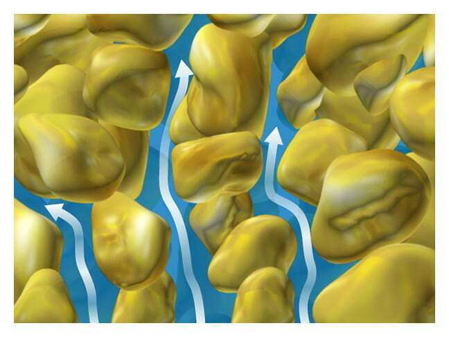
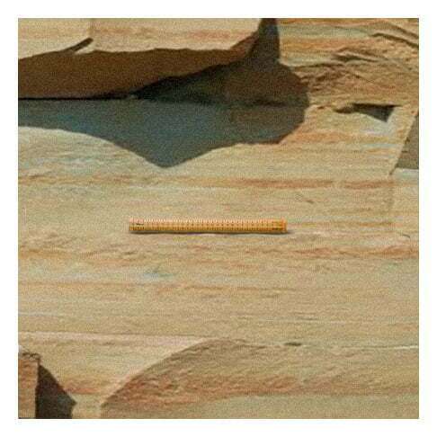
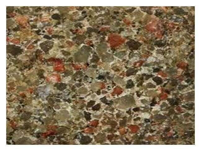
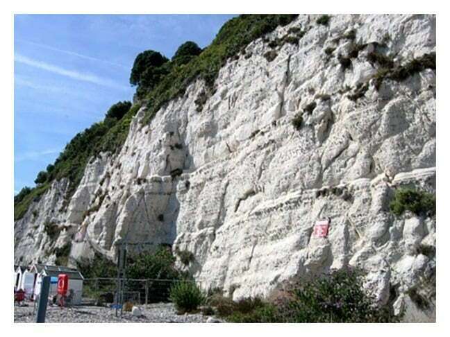
Permeability is related to the rock’s textural properties. Fine-grained sandstones (Figure 6) and intercrystalline limestones have, in general, small pores and moderate to low permeability. Coarse-grained sandstones (Figure 7), fractured limestones and oolitic limestones generally have large pore channels and higher permeability. Combinations of low matrix permeability with high fracture permeability can still result in prolific reservoirs, such as a number found in Iran, Iraq and the North Sea (Figure 8).
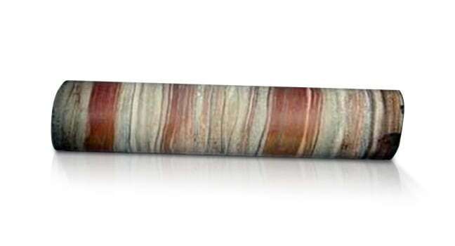
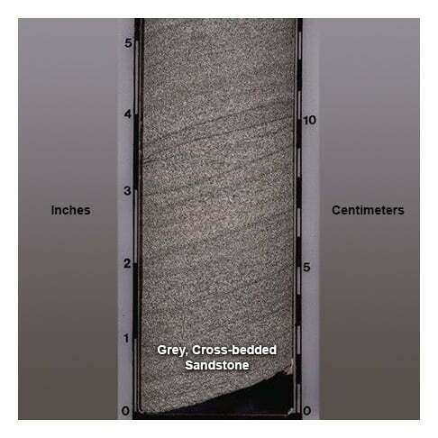
Sample Selection
Core plug samples selected for permeability measurements are normally drilled from full diameter cores parallel to bedding planes (Figure 9). This is easily accomplished in most formations, but some others (such as many aeolian and some fluvial deposits), have visible cross-bedding (Figure 10) in the plugs selected. If vertical permeabilities are required, a second plug is drilled perpendicular to the predominant bedding planes. Measurement of this vertically drilled core plug will indicate the degree of permeability reduction caused by impermeable horizontal layers, or grain orientation.