Related Articles

Finding Hydrocarbon Accumulations
Geologic Elements
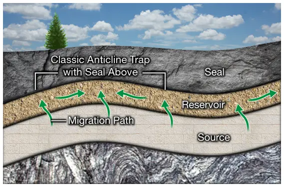
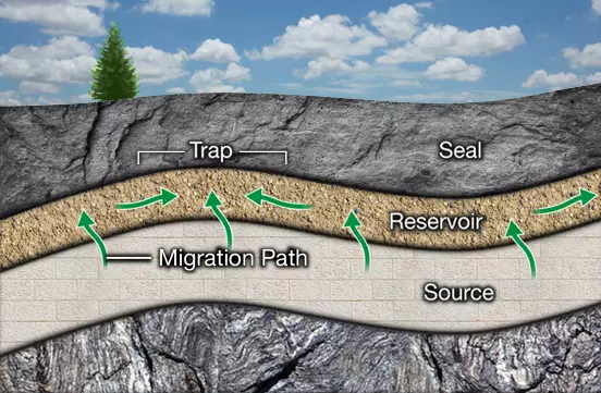
Five geologic elements, collectively known as a hydrocarbon system, must exist for hydrocarbon accumulations to occur (Figure 1):
- Source rock
- Reservoir rock
- Migration path
- Trap
- Seal
Figure 1 shows the location and relationship of the source, reservoir, migration path, trap, and seal.
Other elements that are important in a hydrocarbon system are timing the order in which each of these elements formed and maturation did the reservoir reach a sufficient depth in order for hydrocarbons to form.
Source Rock
Source rock is likely to be a thick shale or limestone (Animation 1 and Figure 2), containing organic material. Ideally, this rock and its organic content are deposited under anoxic, or low oxygen conditions, which are favorable for the preservation of the organic material. The organic material becomes rapidly buried, and matured, at a favorable temperature for a sufficient amount of time.
The nature of the petroleum generated from this process depends on the temperature and burial history, and on the origin of the organic material. In a hydrocarbon system there are two main forms of organic material: woody-plant detritus or marine detritus. These two types of organic material will often dictate the type of hydrocarbon to expect – oil or gas.

In the context of the source rock, the following parameters must be identified:
- Rock type
- Rock volume
- Conditions of deposition
- Temperature and burial history
- Original organic content
Geophysical methods make informative contributions to all these parameters except original organic content, which are gained through core sampling and laboratory analysis.
Reservoir Rock
Reservoir rock is likely to be a porous sandstone or carbonate (Animation 2 and Figure 3). In the best case, this rock is very thick and/or laterally extensive, with high porosity and permeability.
Porosity depends on grain character and depositional conditions. It can be decreased due to cementation or increased due to solution or chemical change.
Permeability depends on pore throat size between grains, which allows fluid to move through the rock. Permeability may be decreased due to cementation, or increased due to fracturing and faulting, where porosity and permeability are seldom uniform throughout the reservoir.

In the context of the reservoir rock, the following parameters must be identified:
- Rock type
- Thickness, both extent and volume
- Conditions of deposition and shape
- Porosity
- Permeability
Geophysical methods are used to identify all reservoir rock parameters except permeability. Recent studies suggest that permeability can be obtained from seismic data through several manipulation techniques which can be time consuming and still have a high level of uncertainty. Geophysical methods can also indicate the type of fluid present, particularly gas.
Migration Path
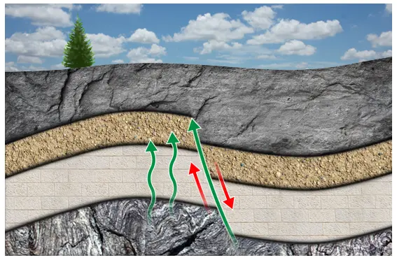
A migration path is necessary for hydrocarbons to move from the source rock to the reservoir rock. The source rock may be a permeable rock or a permeable zone of a fracture or fault (Figure 4). Although current geophysical methods do not measure permeability, some methods may indicate the likelihood of permeable paths. Diagenesis, the physical and chemical changes occurring during burial, also has an effect on permeability.
Trap
A geologic trap is a substructure a rock type or a rock configuration—that blocks the migration path of oil and natural gas. There are a variety of geologic traps which are classified by the following categories:
- Structural traps: anticline fault, salt
- Stratigraphic traps: unconformity, lens, pinch-out
- Combination traps
Structural Traps
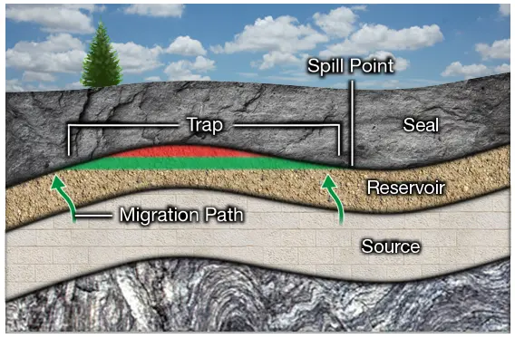
Figure 5 illustrates where hydrocarbons could potentially be trapped beneath an anticline, where green represents oil and red represents gas. In this example, the trap is filled to the spill point, or to the point where fluids begin to flow through the syncline up the adjacent structure.
In structural traps, the reservoir rock itself may be widespread or fairly narrow. The key is to determine the extent of the anticline. Vertical closure may be supplied by a four-way dip (a salt dome) or by a combination of dip and faulting as illustrated in Figure 6.

Stratigraphic Traps
In stratigraphic traps, the reservoir is limited by a change in rock type or sedimentary features. Examples include an unconformity associated with inclined bedding and a seal above, a reef surrounded by an impermeable seal, those traps associated with stratigraphic or depositional pinch-outs, and a sand bar associated with an impermeable seal (Figure 7).
Predicting the extent of these feature improves certainty of a stratigraphic trap and its areal extent.

Identifying Traps in Seismic Sections
Three factors are required for identifying traps:
- Dip of the reservoir rock
- Presence of trapping faults
- Three-dimensional picture of the reservoir body the shape and depositional environment
The suite of traps shown in Figure 8 and Figure 9 compare the shapes of the geologic cross-sections with the seismic sections. These traps illustrate how seismic sections play an important role in the search for structural and stratigraphic traps.
Seismic Section Trap Comparison
Anticline Example
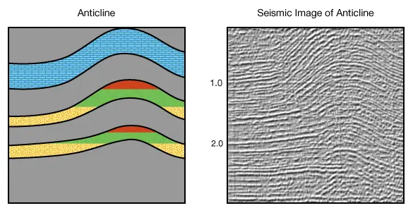
An anticline is a dome-shaped feature formed by compressional forces, where force is applied to a series of sedimentary rock layers that allow those layers to bend and fold. The result is a convex upward structure known as an anticline, which then acts as an area in which hydrocarbons can potentially accumulate. Figure 8 illustrates an anticline with the possible location of hydrocarbons and lists a corresponding seismic image as an example.
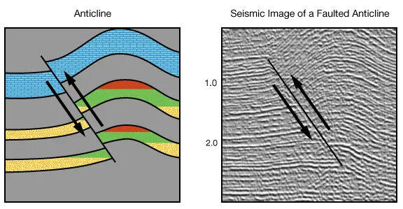
Fault Example
Upon continued compression during the formation of an anticline, the rocks eventually reach a point where they no longer bend, but break instead, thus forming a fault. Figure 9 illustrates a faulted anticline with a corresponding seismic example, and the possible location of hydrocarbons.
Reef and Stratigraphic Pinch-out Example
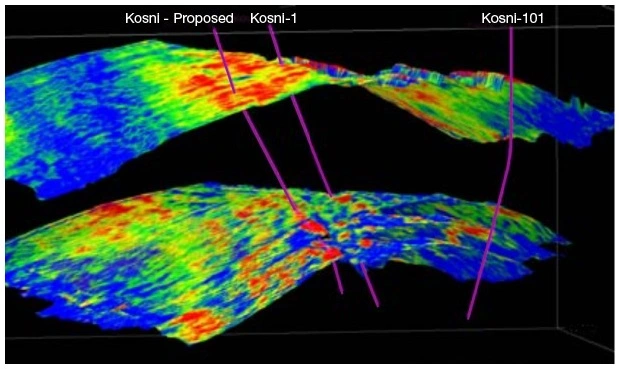
Reefs are the result of an accumulation of sediment particles, or a biotic community, that builds upward from the seafloor in relatively shallow water, less than 30 meters. Over time, as the reefs cease to form, normal sedimentation occurs around and over these reef structures. The sediment layers then become progressively thinner to the point of pinching out against the reef structure creating what is known as a stratigraphic pinch-out. Depending on the nature of the sediments, if the pinch-out comprises coarser grained material than the material surrounding it, it could then act as a reservoir. The reef structures themselves are often quite porous and can also act as a reservoir. Figure 10 shows a reef example with associated stratigraphic pinch-outs, as well as a 3D seismic view of a reef in the central North Sea.

3D Cross-section Salt Dome Example
Sediment can pinch out against a salt dome. Salt domes are a significant barrier to flow. Therefore they provide a good seal associated with stratigraphic pinch-outs. Stratigraphic pinch-outs related to salt domes are often a focus of exploration. Figure 11 shows a 3D image of a salt dome with a corresponding cross-section of what the stratigraphy may look like.

Seal
Geophysical methods can identify the following seal parameters:
- The nature of the rock above the trap
- The fracturing in that rock
- If a system of fractures vents either directly or indirectly to the surface
- If a fault is sealed
- If an unconformity is present, is it sealed
- If there are lateral facies changes, does it represent a seal
Figure 12 illustrates how a seal may be an impermeable caprock, such as a thick layer of salt, unfractured shale, or dense and unfractured limestone. Alternatively, the seal may be a fault where sealing minerals precipitated from compaction water escaping up the fault. In stratigraphic traps it may be a lateral transition. When this occurs, it is known as a facies change, where permeable reservoir rock changes to an impermeable sealing rock.