Related Articles

State of the Rock Matrix
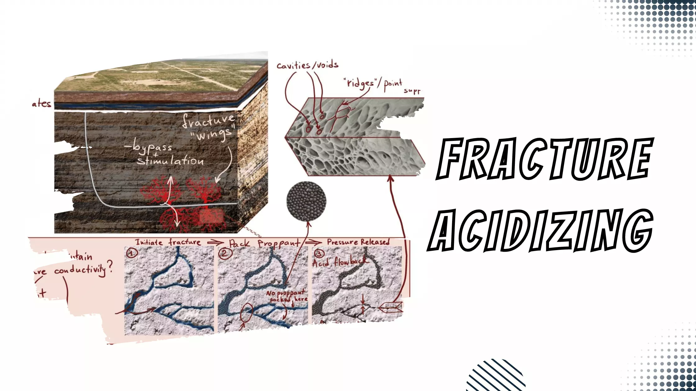
The state of the rock matrix is determined by in-situ conditions. The least principal stress in the reservoir is equivalent to the fluid pressure required to hold open an induced fracture. It is also referred to as closure stress or closure pressure. It is often convenient to report this quantity as a fracture gradient, which is defined as the least principal stress divided by depth, and represented by the slope of the straight line in Figure 1. As depth increases, the fracture gradient deviates from this straight line behavior.
The fracture gradient is normally calculated from pressure measurements taken during injection tests. If it is considered a constant for all wells in the same reservoir, the stress state around one well can be extrapolated to another well. As the reservoir pressure varies, the least principal stress and the fracture gradient vary simultaneously.
Pore pressure (Ppore) influences the effective stresses in a formation via the poroelastic constant. The change in pore pressure in a zone of interest – for example due to reservoir pressure depletion – brings about a change in the same direction (but lesser magnitude) of the least principal stress.
The presence of higher pore pressure in a formation adjacent to the one being fractured increases the tensile forces present in that adjacent zone. This condition requires a lower internal hydraulic pressure to initiate failure via rupture, which can actually cause a fracture to grow into the adjacent formation. Conversely, an adjacent low-pressure formation puts that area of the formation in compression and causes it to serve as a fracture barrier. The barrier stops continued fracture growth, or possibly diverts fracture growth in another direction. An accurate understanding of the pore pressures in the pay zone and in the surrounding formations is critical to predicting both the height containment of vertical fractures and the fracture geometry.
Rock density varies with depth as follows:

Where
 total vertical stress due to overburden
 acceleration due to gravity
 depth
depth
 true vertical depth
 rock density
The total vertical stress consists of two elements:
- Grains in the rock matrix support one another up the geologic column.
- Fluid in the rock’s pore spaces support a column of fluid extending upwards through the porous sediments overlying the formation of interest.
The effective vertical stress ( ) on a rock formation is the total vertical stress minus the pore pressure weighted by the poroelastic constant (α).

The minimum effective horizontal stress due to the overburden can be estimated by “translating” the effective vertical stress using Poisson’s ratio  .
.
The total horizontal stress can then be determined by adding back the poroelastic term.

The total horizontal stress can then be determined by adding back the poroelastic term.

In an actual subsurface environment, there are additional elements to horizontal stress. Along with overburden, tectonic forces created by geological events induce stresses in the formation, as evidenced by structural features such as faults, folds and natural fractures. Nonetheless, the equation above highlights several important observations:
- A decrease in pore pressure causes a decrease in the fracturing pressure. It is often observed that the least principal stress decreases with depletion. The injection of fluid and the resulting temporary increase in pore pressure may also increase the least principal stress.
- The equation explains the existence of large stress contrasts between adjacent layers. Although the overburden is essentially identical, a difference in Poisson’s ratios can cause higher least principal stress in the layer with the larger Poisson’s ratio.
- The fact that the least principal stress is vertical at shallow depths can be explained if we accept that horizontal stresses are “frozen traces” of some prior geological state, but erosion of the surface has decreased the overburden. Consequently, for shallow formations, the vertical stress can be less than the “frozen” horizontal stress.
- For deeper formations, the ratio of horizontal stress to vertical stress approaches
 and hence the horizontal stress is less than the vertical stress.
 - Tectonic stresses due to geologic movements can cause a large scatter around the theoretically calculated stresses. It is generally accepted that a fracture gradient of less than 0.7 psi/ft in a tectonically relaxed reservoir indicates that a vertically oriented fracture will be created, because it is easier to part the earth than to lift it. A fracture gradient greater than 1.1 psi/ft (which is in agreement with the generally accepted value for the normal overburden gradient) is indicative of a serious anomaly specific to the formation.
 and hence the horizontal stress is less than the vertical stress.
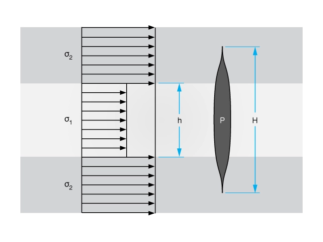
Knowing the vertical profile of the minimum horizontal stress is essential for two reasons. First, the value calculated for the center of the perforations in a fracturing job will be the base pressure to which net pressure is added to obtain the fracture propagation pressure. Second, a positive stress contrast in the neighboring layers is believed to be the most important controlling factor for fracture height containment (Figure 2).
Because a detailed depth-to-depth determination of the minimum stress might be impractical, several methods have been developed for using available well logs to predict vertical stress variations. Most of these methods are reliable only if used after calibration. The calibration process involves correlating the log with known values of the minimum stress for at least one well in the formation. The known values of the minimum stress are obtained from calibration fracturing treatments, several variations of which are known as: micro-fracturing, step-rate test, pump-in flow-back test, or mini-frac closure pressure determination.
In addition to the magnitude of the least horizontal stress, its orientation is also of interest because it controls the orientation of the induced fracture. Several methods are available for estimating the principal stress orientation. One group of measurements uses oriented core samples, such as an elastic strain relaxation. Another group includes tiltmeter or similar measurements in open hole. Acoustic measurements on an oriented core sample and acoustic logs of the open hole can also provide information on the orientation of the least principal stress.
Stress Anisotropy and Natural Fractures
Stress anisotropy refers to differences in the magnitude of the stresses within a formation depending upon the direction of measurement. Stress anisotropy is important in naturally fractured reservoirs because it influences the orientation, density and width of the fractures. These factors obviously affect reservoir flow characteristics and well deliverability. But the orientation, density and character of natural fractures can also influence the dimensions and orientation of hydraulically created fractures.
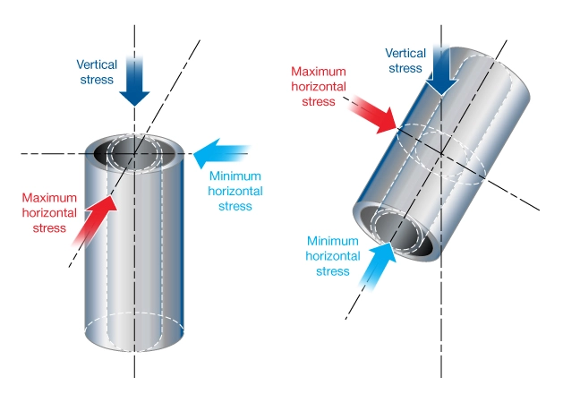
Stress anisotropy around the borehole can also affect wellbore stability, leading to wellbore “breakouts” (hole enlargement due to spalling of the rock). For vertical and horizontal wells, borehole breakouts occur in the direction of minimum principal stress (Figure 3). In vertical wells, the wellbore instability is mainly affected by the horizontal stresses, since the wellbore is oriented in the direction of the vertical stress. For horizontal wells, the stresses applied to the wellbore wall depend on the wellbore direction. In a normal stress regime, the difference between vertical and maximum horizontal stresses is less than the difference between vertical and minimum horizontal stresses. Therefore horizontal drilling in the direction of minimum stress can result in fewer wellbore instability issues, compared with drilling in the direction of maximum stress (Bahrami et al. 2010). The dominant factor in the instability mechanism is the high degree of anisotropy between principal stresses.
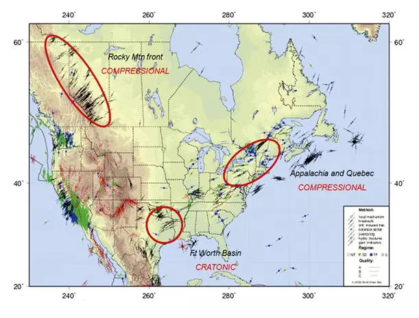
Stress anisotropy is caused by variations in earth stresses on multiple scales from near-wellbore, to field, to basin. Natural fractures generally develop in the vertical plane and open normal to the least horizontal stress, and thus are likely to be oriented parallel to the maximum horizontal stress (Figure 4). The orientation of natural fractures is often unrelated to the present-day stresses in a formation but rather to paleo stress regimes that no longer exist. The orientation and density of natural fracture sets may vary within a region, even if the regional stresses are relatively constant in orientation.
Understanding both the current stress regime and the pre-existing natural fracture characteristics are important in the design of hydraulic fracture treatments. This is even more the case when the hydraulic fractures are created along a horizontal wellbore that has its own orientation relative to both the natural fractures and formation stresses.
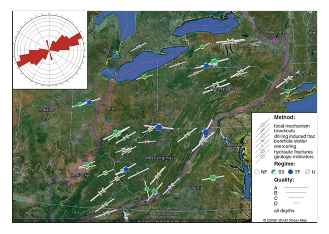
For example, two primary vertical fracture sets are present in the Marcellus Shale in the US Appalachian basin. These are referred to as the J1 and the J2 fractures (Ellison, 2014). The J1 fractures, oriented northeast to southwest, were formed during the Alleghenian Orogeny and are parallel to the current regional maximum horizontal stress orientation in the Appalachian Basin (Figure 5). The J2 fractures, formed during a subsequent period of hydrocarbon generation, are oriented northwest to southeast and thus cut across the older J1 fracture set.
Both J1 and J2 natural fracture sets have similar apertures. However, the older J1 fractures are not mineralized and are also more prevalent and closely spaced than the J2 fracture set.
Ideally, a horizontal well attempting to maximize productivity from the Marcellus Shale should intersect and hydraulically activate the J1 fracture set to exploit its high permeability, and should hydraulically activate the J2 fracture sets in order to connect to parallel J1 fractures. If the J2 fracture sets are stimulated, inevitably they will intersect with J1 fracture sets, allowing production from those fractures. Operators drilling in the Marcellus Shale have found that horizontal well lateral azimuths oriented northwest to southeast (nearly perpendicular to the maximum horizontal stress) activate both the J1 and J2 fracture sets and yield the highest production rates.