Related Articles

Fracture Initiation and Growth
At the beginning of a hydraulic fracturing treatment, fluid enters the formation in a radial flow pattern. Maintaining the fluid injection rate above the formation’s maximum matrix flow capacity, as defined by Darcy’s law, continually increases the flowing pressure at the wellbore. Eventually, the pressure increases until the rock ruptures in tension and a fracture is created.
The orientation of the fracture is perpendicular to the direction of the least principal stress (Figure 1).
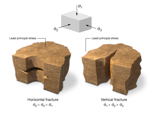
This is most easily understood by realizing that for a fracture to form, a portion of the reservoir must undergo physical deformation. The direction in which it is easiest to push or deform the rock is the one exerting the least resistance or least stress. Thus, the fracture forms at a 90-degree angle to this stress direction.
The vertical stress results from the weight of the overburden, and is partially translated to horizontal stresses. At sufficient depths (usually below 1000 m or 3000 ft) the minimum principal stress is horizontal; therefore, the fracture faces are vertical or nearly vertical. For shallow formations, the minimum principal stress is vertical, resulting in horizontal fractures.
In the near-wellbore region (within a distance of two to three times the wellbore diameter), the description of fracture orientation becomes more complicated. The drilling process disturbs the formation’s original stress state, resulting in a minimum principal stress direction that is different from the far field direction. Also, casing perforations and pre-existing micro-fractures may “guide” fracture orientation, at least at the initiation stage. It is important to remember, however, that such disturbances are localized within the vicinity of the wellbore. Once the fracture has extended far enough, the far field stress state dominates its orientation.
Fracture Growth
After breakdown, a portion of the fluid entering the fracture leaks off through the exposed faces of the fracture. The remaining fluid continues to extend the fracture as long as sufficient hydraulic pressure is maintained and the injection rate is greater than the rate at which the injected fluid leaks into the formation. Fracture growth is generally assumed to be confined to a single plane that is perpendicular to the least principal stress. Within this plane, a fracture continues to propagate equally in all directions until it encounters a barrier limiting growth in a particular direction (Figure 2).
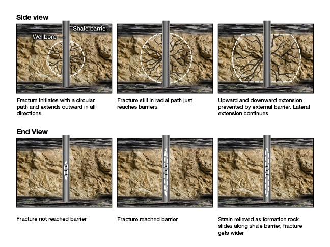
Simultaneously with fracture propagation, the fracture’s average width is also expanding. In fact, lateral fracture propagation, fracture height growth and fracture width inflation are competitive processes. The ultimate created fracture geometry depends on how these processes share the injected fluid volume in excess of fluid leakoff.
A fracture growth barrier is anything that limits the extension of a fracture in any direction. Barriers may be:
- Overlying or underlying zones having significantly different properties of elasticity than the zone being fractured
- Rocks having a higher tensile stress, high-stress loadings, or stress loadings in which the least principal stress is in a different direction than at the wellbore
- Rocks having higher fracture gradients, or zones having lower pore pressures
- Slippage planes unique bedding planes having no vertical bonding, in which the adjacent surfaces act almost as if they are lubricated, and which dissipate the dynamic growth energy of a fracture
- Physically intruded solids, such as propping agents
In short, fracture barriers may be combinations of any or all of these factors. Many of these factors are difficult to measure or even estimate. The variation of minimum principal stress from layer to layer is, however, more accessible and is considered to be the main factor controlling height containment and growth.
Fractures in Horizontal Wells
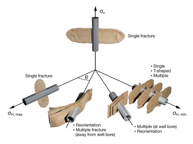
In horizontal wells, the orientation of the fracture relative to the wellbore is dependent on wellbore orientation as well as the orientation of the least principal stress (Figure 3).
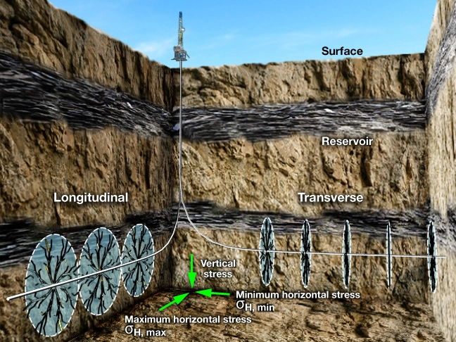
Fractures can be longitudinal or transverse, and may reorient if the horizontal lateral is not aligned with the least principal stress direction (Figure 4). Typically, well trajectories are oriented to maximize the likelihood of multiple transverse fractures, as this approach maximizes the total volume of reservoir rock affected by the fractures. The total number of fractures, as well as their placement, must be such that interference between fractures is minimized.