Fluid Loss Control
Fluid loss results from several sub-processes that occur in concert along different zones of the fracture.
- Polymer-based fracturing fluids continually build up a filter cake at the fracture face as fluid leakoff into the formation matrix leaves particles against the fracture face. This filter cake creates a resistance to further flow. The greater this resistance, the less pressure is available for driving the fluid into the formation.
- In the near vicinity of the fracture face there is an invaded zone influenced by the fracturing fluid. Here, there is a distinction between a polymer-invaded zone and a filtrate invaded zone:
- In the polymer-invaded zone, fluid flow is defined by non-Newtonian polymer rheology.
- In the filtrate-invaded zone, the flow is Newtonian and the filtrate fluid viscosity is effectively that of water.
- Finally, there is the bulk of the uninvaded reservoir containing the original formation fluids. The response of the reservoir to the fluid leakoff process is determined by the reservoir and fluid characteristics.
It is important to understand that the makeup of the fracturing fluid can affect the filter cake and the depth of a polymer-invaded zone, but overall leakoff behavior is mainly controlled by the formation and remains relatively unaffected by fracturing fluid additives.
Fluid efficiency can be improved by adding gelling agents or special fluid-loss additives. Viscosifiers added to base fluids increase the fluid viscosity, thereby increasing pressure drop both through the filter cake and the polymer-invaded zone. Insoluble or slowly soluble fluid-loss additives create a thin skin of additional filter cake to reduce the leakoff rate.
The leakoff velocity for a given fluid is related to the overall leakoff coefficient (![]() ) and the time elapsed from the start of the leakoff process as follows:
) and the time elapsed from the start of the leakoff process as follows:
![]()
Where
![]() leakoff velocity
leakoff velocity
![]() leakoff coefficient
leakoff coefficient
![]() time elapsed from the start of the leakoff process
time elapsed from the start of the leakoff process
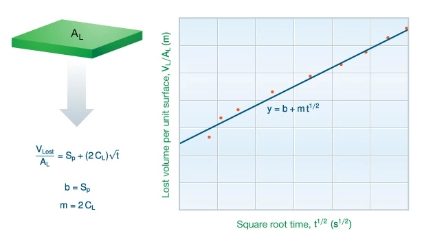
The volume of fluid passing through fracture surface area from time zero to time t is:
![]()
Where
![]() fracture surface area
fracture surface area
![]() spurt loss coefficient
spurt loss coefficient
![]() fluid volume passing through fracture surface area from time zero to time t
fluid volume passing through fracture surface area from time zero to time t
![]() overall leakoff coefficient
overall leakoff coefficient
The overall leakoff coefficient for a particular fluid/geology combination can be estimated using laboratory measurements of fluid loss as a function of time. These measurements can be plotted and the slope of the line used for both the spurt loss and overall fluid loss coefficients (Figure 1). These can be used as a source of useful information helping the fracturing design engineer compare the performance of fracturing fluids relative to each other.

However, as far as the quantitative determination of the overall leakoff coefficient is considered, prediction from laboratory measurements is of limited value. Instead, a pre-job fracture calibration treatment or mini-frac should be carried out to obtain this information.
 Petro Shine The Place for Oil and Gas Professionals.


