Related Articles

Fracturing Fluid Rheology
Rheology the study of the flow or deformation of matter is an important concept in fracturing fluid design. The rheological properties of a fracturing fluid affect all of its design characteristics, including leakoff rate, proppant transporting ability, frictional pressure losses during pumping and post-fracturing well cleanup capability.
Fluid rheology is generally concerned with two quantities: shear stress and shear rate. To define these quantities, consider a fluid that is located between two parallel plates (Figure 1).
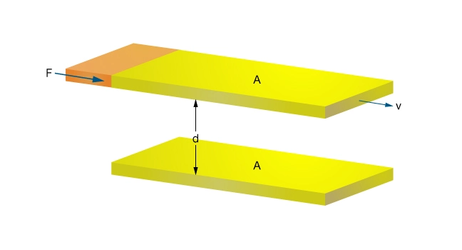
If a force ( ) is applied to the upper plate while the lower plate is held stationary, the upper plate attains a constant velocity (
 ). The magnitude of v depends on the magnitude of F, the distance between the plates (
 ), the surface area (
 ) and the fluid viscosity (
 ):
):

The force per unit area is defined at the shear stress ( ):
):

while shear rate ( ) is equal to the fluid velocity divided by the distance between the plates (
 ). Therefore,

Newtonian Fluids
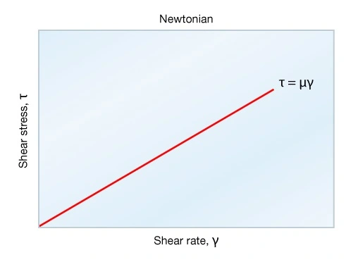
Where viscosity is a constant, there is a direct relationship between shear stress and shear rate (Figure 2). The fluid viscosity corresponds to the slope of the straight line. A fluid described by this relationship is referred to as a Newtonian fluid. The best example of a Newtonian fluid is water.
Non-Newtonian Fluids
Non-Newtonian fluids exhibit a non-linear relationship between shear stress and shear rate. Viscosity is not constant, but has a value that varies according to the shear stress and shear rate. Most fracturing fluids are non-Newtonian, with a shear stress-shear rate relationship that can most simply be described using a power law or pseudoplastic model (Figure 3).
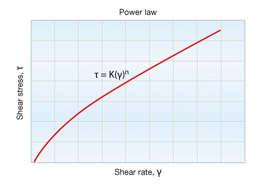
This model illustrates a key concept: viscosity decreases with increased shear rate a phenomenon known as shear-thinning behavior.
Power law fluids exhibit a linear relationship between shear stress and shear rate when plotted on log-log paper. The shear stress can be written as shown in Figure 3, where K is termed the consistency index, and n is the exponent, referred to as the Power Law Index. The apparent viscosity of a power law fluid is related to the shear rate through these two indices.
Flow Regimes
The flow regimes most commonly encountered in well completion and stimulation operations are laminar, turbulent and transitional.
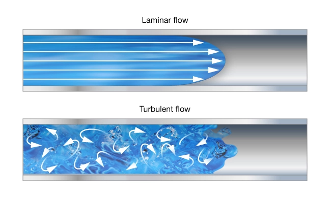
- In laminar flow, fluid behaves as a series of parallel layers moving at uniform or near-uniform velocities. There is no large-scale movement of fluid particles between layers. The fluid layers nearest the center of a pipe (or other conduit) move faster than the layers adjacent to the pipe wall (Figure 4 A).
- Turbulent flow is characterized by velocity fluctuations among the fluid stream particles, both parallel and axial to the mean flow stream. These fluctuations break down the boundaries between the fluid layers, resulting in a chaotic flow pattern (Figure 4 B).
- Transitional flow exhibits characteristics of both laminar and turbulent regimes. It describes the often hard-to-define region where flow is neither wholly laminar nor wholly turbulent.
Of particular importance in hydraulic fracturing are the laminar flow regimes in two limiting geometries: slot flow and flow in a limiting ellipsoid (Figure 5).
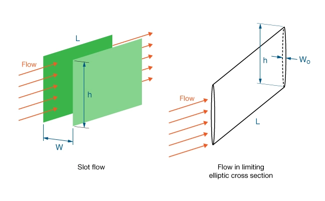
Slot flow occurs in a channel of rectangular cross section with an extremely large aspect ratio (ratio of the longer side to the shorter side). Limiting ellipsoid flow occurs in an elliptic cross section with an extremely large aspect ratio.
If a fluid is Newtonian, simple expressions are available to calculate pressure drop as a function of the viscosity:
Slot flow: 
Flow in limiting elliptic cross section: 
Where
 pressure drop
 length
 viscosity
 average velocity
 width of slot
 maximum width of elliptical cross-section
If a fluid is non-Newtonian, an equivalent viscosity can be determined which, when substituted into the Newtonian expression, gives the correct pressure drop:
Slot flow: 
Flow in limiting elliptic cross section: ![\qquad \mu_e = \dfrac{2^{n-1}}{\pi} \left[ \dfrac{1 + \left( \pi - 1 \right)n}{n} \right]^n \cdot K\, w_0^{1 -n}\cdot u_{ avg} ^{n - 1}](https://petroshine.com/wp-content/ql-cache/quicklatex.com-c58164ffb6acc43d51a53920eb0ec326_l3.png "Rendered by QuickLaTeX.com")
Where
 equivalent Newtonian viscosity
 flow behavior index
 consistency index
average velocity
width of slot
 maximum width of elliptical cross-section
The equivalent viscosity is not the same as the apparent viscosity, because it is related to one specific flow geometry and reflects the specific shear rate profile in that geometry.
In calculating the friction pressure drop through tubulars, well-known turbulent flow correlations are less useful for fracturing fluids and special relations have to be applied because of the drag reduction phenomena caused by the long polymer chains.
Proppant-Carrying Ability and Friction Loss
Fluid viscosity is of paramount importance in proppant transport. We can estimate the settling velocity of an individual proppant particle in a power law fluid (assuming the viscosity is great enough to ensure laminar settling) using a generalization of Stokes’ Law:
![v_s = \left [\dfrac{d_{p}^{1+n'} \left ( \rho _p - \rho _f \right )g}{18\, K'} \right ]^{\frac{1}{n'}}](https://petroshine.com/wp-content/ql-cache/quicklatex.com-0bda8f39135e7faf0b2dbcbdcd6e8d8d_l3.png "Rendered by QuickLaTeX.com")
Where
 particle settling velocity
 proppant diameter
 proppant density
 fluid density
 flow behavior index
 consistency index
 acceleration due to gravity
A low settling velocity will permit proppant to be transported farther into the fracture before settling out.
The velocity is directly proportional to the density difference between the proppant and the fluid, as well as the proppant diameter. Using this equation provides only order-of-magnitude accuracy, because the settling shear rate usually falls outside the validity range of the power law model. Still, it is often enough to answer the main question: Is the settling velocity low enough to consider the fluid to be suitable for good proppant transport?
When a lower viscosity fluid is used, the proppant continually settles toward the bottom of the fracture as the fluid moves away (Animation 1). A bed of proppant is then deposited at the bottom of the fracture, gradually building up in a dune-type depositional pattern. The “proppant pack” width is equal to the dynamic hydraulic fracture width. The pack height is determined by the critical velocity required to move proppant laterally over the top of the proppant pack.
Proppant buildup at the bottom of a fracture due to rapid settling of proppant Animation
The propped fracture length is usually much less than the created fracture length. The pack height continues to increase after pumping has stopped, since those proppant particles still in suspension at that point continue to settle. Settling continues until the fracture has closed on the proppant. The resulting geometry of the proppant bed is difficult to predict. In situations where the fracture extends out of zone into the lower bounding bed, much of the proppant may be placed out of the pay formation.
When a more viscous fluid is used, proppant settling is negligible and a much larger portion of the total created fracture height is propped. After closure, the width of the proppant pack is more uniformly distributed in both the vertical and lateral directions than it is in the case of a proppant drop-out prone fluid.
While more viscous fluids generally have better proppant transport capability, consideration of other important fluid functions suggests using only as viscous a fluid as is absolutely necessary for reliable proppant transport. Although high viscosity is generally desirable, it can result in extreme frictional pressure losses when pumping the fluid through the wellbore tubular configuration down to the perforations. Fortunately, this friction loss is less tightly related to viscosity in the turbulent flow regime than in the laminar flow regime, especially for polymer-based fracturing fluids. Long linear polymer chains have a tendency to suppress turbulence. As a result, viscous fracturing fluids exhibit a so called “drag reduction” phenomenon and exhibit less frictional pressure loss at high pump rates than is predicted from correlations valid for Newtonian fluids, although they will still be higher than for less viscous fluids. Frictional pressure loss in the wellbore tubulars requires an increase in pumping horsepower, which is directly related to fracturing treatment cost.
Temperature Sensitivity
Fracturing fluid properties are sensitive to temperature, and temperatures outside of the treatment design parameters can have a detrimental effect on job performance. The use of temperature stabilizers is one way to delay viscosity degradation at higher temperatures; for low-temperature wells, additional viscosity breakers may prove useful. For very small treatments, the exposure to high temperature may not last long enough for fluid degradation to become a serious concern.
Other ways of overcoming high temperature sensitivity include pumping larger fluid volumes to cool down the fracture face, or pumping faster to reduce the exposure time. An inexpensive cool-down pre-pad can be pumped ahead of a high-efficiency fracturing fluid to better utilize the capabilities of the more expensive fluid. High-temperature fluid systems and special cool down techniques are also available, which permit the effective fracture stimulation of wells having a static bottomhole temperature in excess of 400 °F.
It can be equally challenging to design fluid systems for use in shallow, low-temperature wells. Conventional viscosity breakers used in crosslinked fluid systems have to reach a certain triggering temperature before they can initiate viscosity reduction. Thus, shallow wells typically call for linear (non-crosslinked) fluids that are poorer at proppant carrying.