Related Articles

Stress
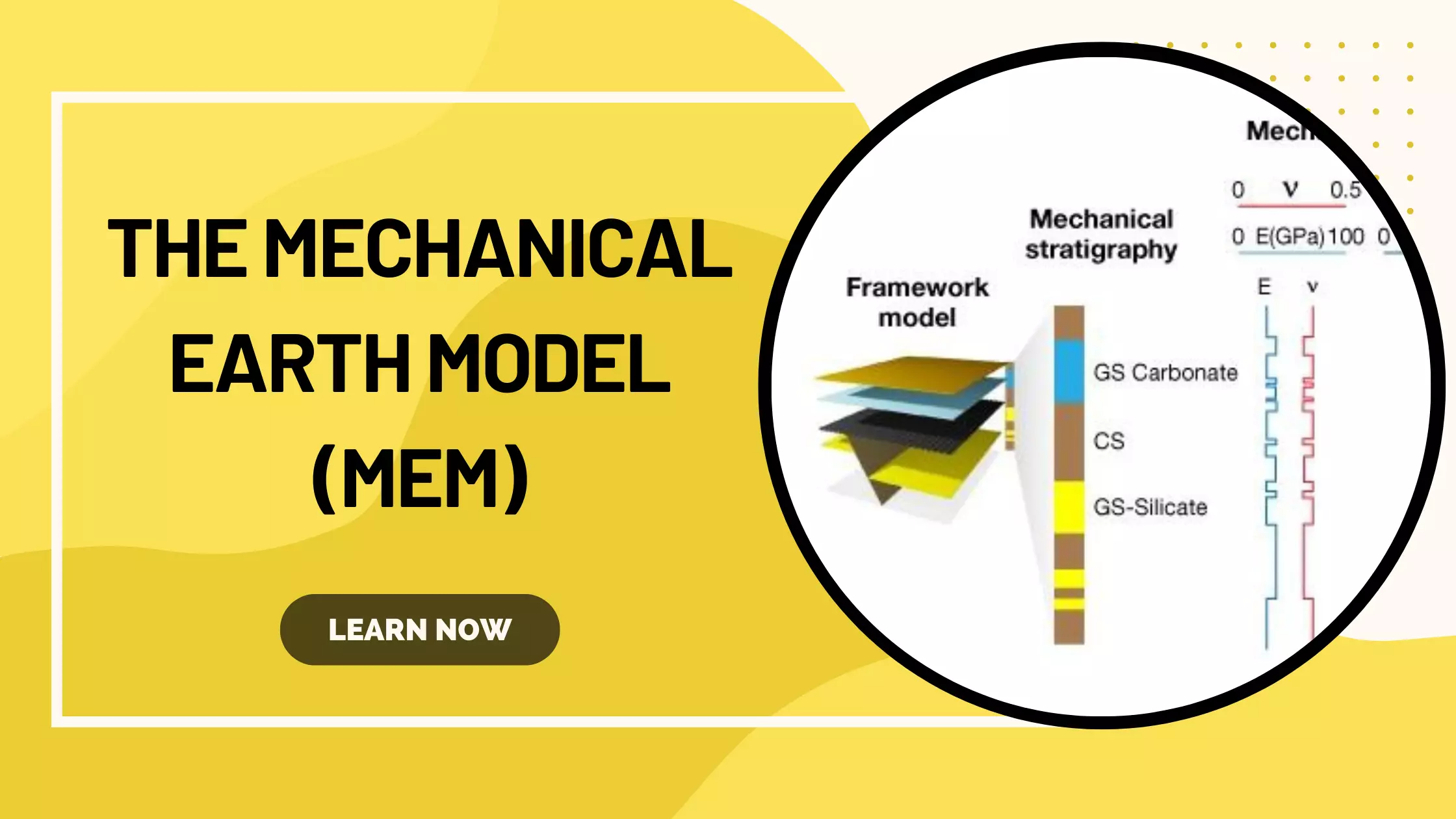
Developing information about earth stress and rock mechanical properties requires integration of information obtained over a length of scales covering 11 orders of magnitude. Clay-size particles (~10-6m) represent the smallest scale, and sedimentary basins (~105m) represent the largest scale. Attention to the small scale is important for understanding how rock deforms under a given state of stress. Attention to the large scale is important for establishing initial estimates of the contemporary state of stress.
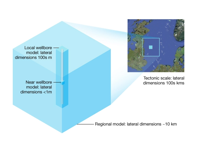
Characterizing the structural framework and rock properties within large regional volumes of interest (VOIs) is the domain of 3D seismic interpretation and inversion. Typical regional VOIs are 5000 km3 or more. Within the regional models are more local and detailed “single-well” and “near-wellbore” models. Local models can extend over the length of the well as in the case of drilling and subsidence applications. They can also be restricted to reservoir intervals as is the case for hydraulic fracturing and sand management applications. At the near-wellbore scale and within the reservoir, petrophysical data and core data are often available for detailed geomechanics modeling. Figure 1 illustrates the spatial domains of interest for geomechanics modeling.
The concept of stress is fundamental to all geomechanics models and applications. Due to the geologic time scale in which rocks are deformed, present day stress is measured in-situ and data is used in controlled laboratory experiments and in engineering operations like drilling, hydraulic fracturing, and reservoir production. Stress is defined as force per area:

Stress acting at a point on the interior of a solid body is defined as the limit of the ratio, force divided by area:

Figure 2 shows a force vector (F) acting on a surface (A) and its decomposition into normal force ( ) and shear force (
 ) components.
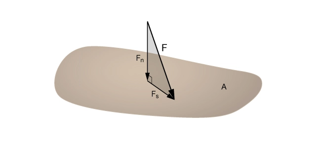
These two components of force give rise to two stress components called normal stress,  and shear stress,
  , where:

and

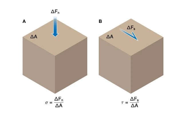
Figure 3 illustrates the effect of normal stress (A) and shear stress (B) acting on an elementary volume of rock. If a force is uniformly distributed over a large area and the ratio FA remains constant as the \delta A diminishes, the stress field is said to be homogeneous over the area A .
However, at the scale of rock microstructure the stress is spatially varying and the stress field is inhomogeneous. Consider two rock grains in contact and subjected to a vertical force F illustrating stress concentrations within granular rocks (Figure 4).
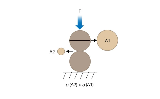
Since  , the stress at the grain contact is greater than in the middle of the grain.
Compressive and Tensile Stress
Compressive stress tends to push particles together; tensile stress tends to pull particles apart (Figure 5).
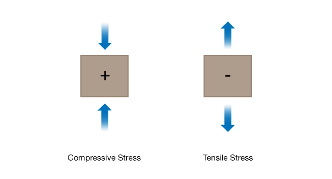
The sign convention used in rock mechanics is that compressive stress is positive and tensile stress is negative. (Note: this is the opposite of the sign convention used in mathematics and engineering mechanics.)
Stress Tensor
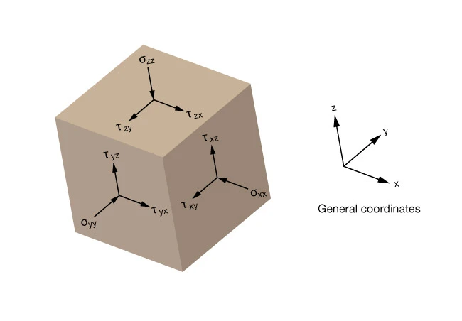
The state of stress at a point in a solid body is defined completely by six quantities of the stress tensor ( ) . They include the three normal and three shear stresses acting on orthogonal surfaces defined with reference to an arbitrary set coordinate axes (x,y,z) . For example,
  is the normal stress acting on the x plane due to a stress applied in the direction of the x axis.
  is the shear stress acting on the x plane due to a stress applied in the y direction. The other stress components are similarly defined.

Figure 6 illustrates the stress tensor on a reference cube referred to general coordinates.
Principal Stress
Principal stresses are the components of the stress tensor when the basis is changed in such a way that the shear stress components become zero. Principal stresses are fundamental to geomechanics, and are frequently measured in the field and used to construct geomechanical models and Mohr’s circle diagrams.

For any point in a material, there exists a coordinate system such that the faces of the reference cube are not subjected to any shear stresses. The stress tensor, referred to principal coordinates, has only normal stress terms (Figure 7).
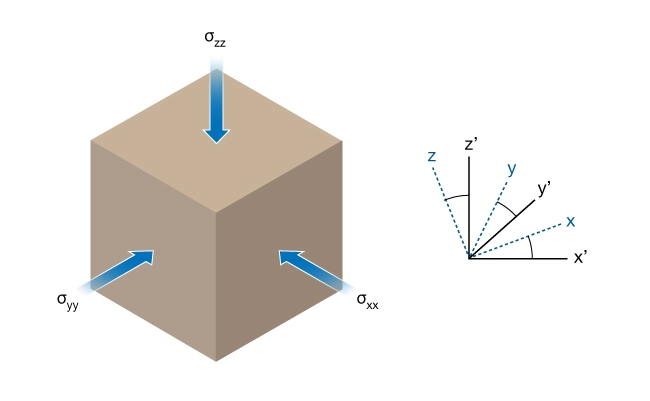
However, to completely define the state of stress at a point, six quantities are still required. These are the three principal stresses and three angles defining the rotation between the principal coordinate system and any other coordinate system.
Note that it is commonly assumed that the vertical stress is a principal stress. When this assumption is valid, the state of stress can be completely specified by three principal stress magnitudes and an azimuth for one of the horizontal principal stress axes. Unless noted otherwise, it will be assumed that one of the principal axes of stress is vertical.
Hydrostatic Stress
Hydrostatic stress is an isotropic state of stress that contributes to volume change in a material. Hydrostatic stress is often used synonymously for hydrostatic pressure (P) . Typically hydrostatic stress or hydrostatic pressure refers to the state of stress in a fluid. In tensor form, hydrostatic stress is a normal stress:

In a solid hydrostatic stress, P is defined as the mean normal stress  such that:

Effective Stress
The concept of effective stress originated in civil engineering. Terzaghi (1943) showed that the deformation of fluid-saturated porous soil is governed by effective stress ( ) . That is, deformation is controlled by the difference between externally applied stress
  and the pore fluid pressure
  . Figure 8 illustrates the effective stress \sigma′ acting at the contact between two grains (red).
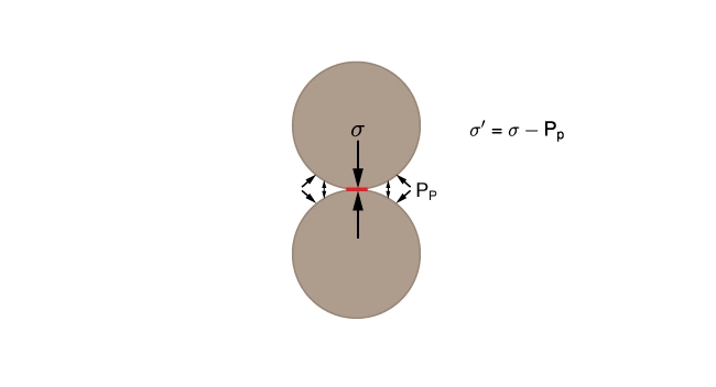
Terzaghi’s effective stress is defined as:

Effective stresses are normal stresses. Effective shear stress is undefined. In principal coordinates, the effective stress tensor is given by:

For many problems in geomechanics, Terzaghi’s effective stress is sufficiently accurate for predicting rock failure.