Related Articles


Air Drilling Equipment
Air Compression Systems
The primary components of the air compression system are:
- Compressors
- Boosters
- Mist pumps
- Air header
We will discuss each in turn below.
Compressors are the main components of the air drilling surface setup. Typically, a diesel engine is used to power air compression units, which can deliver up to 1,000 standard cubic feet per minute of air. The actual air delivery rate can be estimated using:
Equation 1
![Q_{o} = Q \left [ \dfrac{520\ P_{i}}{14.7 \left ( T_{i} +460\right )} \right ]](https://petroshine.com/wp-content/ql-cache/quicklatex.com-ac1c94131bb3105906e972a4c599f148_l3.png "Rendered by QuickLaTeX.com")
where:
Qo = air delivery rate at standard conditions, scfm
Q = free air delivery rate, cfm
Pi = ambient pressure, psia
Ti = ambient temperature, oF
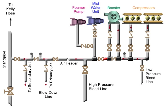
As seen in Equation 1, the wellsite elevation and ambient temperature should be taken into consideration while designing compressor units for air drilling operation. A typical air compression system is shown in Figure 1.
The actual delivery rates achieved by various compressors vary between 50 and 90 percent of capacity.
It is good practice to install orifice meters in field operations to determine actual volumes delivered to the standpipe. Most compressors used in air drilling operations are multi-stage. Their maximum discharge pressure varies in the range of 250 to 350 psig.
Boosters are used to increase the output pressure of the compressors. They also have single-and two-stage types that are typically used for unloading water from casing after cementing operations.
The air header is a component of the surface compression system that delivers the air to the rig’s standpipe manifold. It also contains check valves that protect the compression system from any flow-back.
Since it might be necessary to switch from dry air drilling to mist drilling, mist pumps are always included in an air drilling setup.
Drill String
A standard air drilling string is equipped with two non-return or float valves; one at the bottom and another at the top. They may be either flapper or dart style valves. The lower valve is used to prevent cuttings from flowing back through the bit. It is also used to prevent gas from flowing up the string while tripping.
The upper valve is used to keep the pressurized air in the drillstring during connections. It may not be needed if the standpipe pressures are low. For deeper wells, however, it becomes a standard part of the air drilling assembly. Moreover, there are different types of float valves, which are used to prevent air from flowing down the drillstring in the case of a downhole fire.
Return System
A diverter is placed above the blowout preventer to direct the returning air away from the rig. A rotating head or a rotating BOP are the types of different diverters used in the drilling industry. Figure 2 illustrates the working principle of a rotating control head.
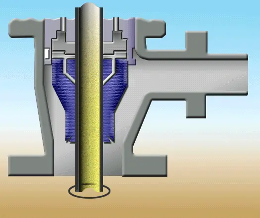
Typically, rotating heads can withstand pressures up to 500 psi, while a rotating BOP can seal up to 1500 psig dynamic drilling pressures. Diverters are not designed to replace existing BOP equipment.
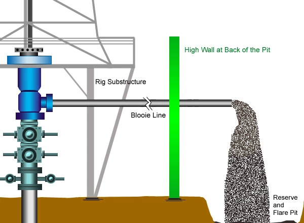
As shown in Figure 3, diverters take the returning air to a flare pit through the blooie line.
The blooie line should be securely tightened in place and should be positioned at 45 degrees from prevailing wind direction. According to regulations, a blooie line should be at least 100 to 150 feet long. As a common practice, blooie lines are sized equal to the diameter of the annulus over the longest section of the well that is drilled with air.
Even during connections, the rotating head is kept in place to divert any gas flow into the blooie line without having to rely on the primary jet. If the compressor delivery is bypassed through a jet line, noise levels will rise significantly, because of its smaller diameter. Otherwise, during normal drilling operations, the noise at the end of the blooie line will be at a reasonable level.
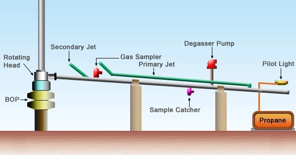
Blooie lines are also equipped with gas detectors that can distinguish hydrogen sulfide from other hydrocarbons. The dusty nature of the cuttings that come out at the end of the blooie line can create potential environmental and health risks. Therefore, a water spray is typically installed at the end of the line to kill the dust. The pilot light at the exit of the blooie line should always be lit in case of possible hydrocarbon production from the well. Depending on the possibility of oil production from the well, a large reserve pit may be required. A typically layout of an air drilling site is illustrated in Figure 4.