General Description
In the early years of rotary drilling , a typical bottomhole assembly (BHA) consisted of nothing more than a short crossover sub, or collar, between the bit and the drill pipe. Over time, drillers observed that penetration rates tended to increase as more weight was applied to the bit,and so they began using BHAs with longer sections of heavy pipe (in keeping with the original terminology, these heavy joints of pipe have continued to be called drill collars).
But even as these heavier BHAs brought improved bit performance, it became clear that applying more weight to the bit involved a trade-off: a greater potential for drill pipe failure due to increased compressive force and resultant bending or buckling.
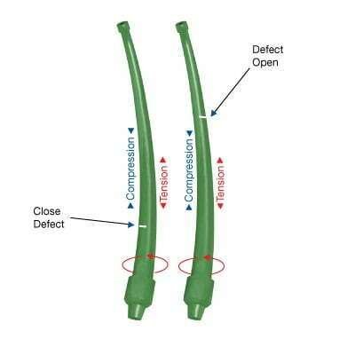
When drill pipe rotates in a compressed state, it experiences cyclic stress reversals. Each rotation of the string causes the drill pipe fibers to go from compression to tension to compression. This high cyclic stress bending causes metal fatigue, which is cumulative and eventually leads to drill pipe failure (Figure 1).

Buckling tendencies are greatest in the pipe body between the end upsets, which is the thinnest and most flexible part of the drill string. The abrupt change in cross-sectional area between the pipe body and the upsets sets up stress concentrations just above and below the much stiffer tool joint.
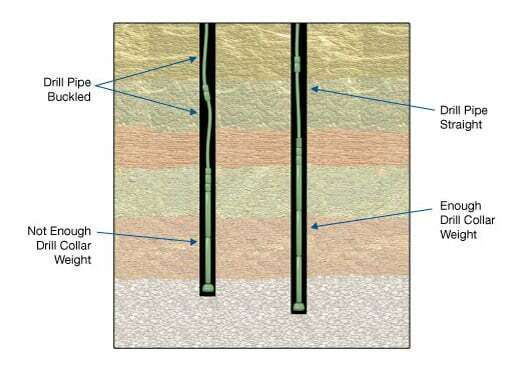
Thus, a fundamental objective in BHA design and drill collar weight selection is to “eliminate the potential for axial and torsional buckling of the drill pipe” (Mitchell, 1995). This is illustrated in Figure 2.

Weight Requirements: Vertical Hole
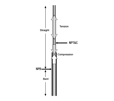
Figure 3 (after Mitchell, 1995) illustrates two points of transition for a drill string in a vertical well:
- The neutral point of bending,or NPB,is the point of transition from a straight to a bent drill string.
- The neutral point of tension and compression (NPT & C) is the point below which the drill string is in compression, and above which it is in tension.
The NPB should always be located in the bottomhole assembly, below the drill pipe. It is this quantity that is of practical interest in drill string design. The NPT&C, on the other hand, is normally located in the drill pipe and is not used in BHA design.

In practical terms, the buoyant weight of the drill collars should correspond to the desired weight-on-bit:
![]() (1)
(1)
where:
(Wdc)air= weight of drill collars in air
BF= buoyancy factor, which is equal to
. For steel drill collars in drilling fluid, ρsolid is equal to 65.5 ppg (7.85 specific gravity), and ρfluid is the drilling fluid density or mud weight (ppg or specific gravity).
WOB= desired weight on bit, based on manufacturer’s recommendations
SF= predetermined safety factor. May range from 1.10 to 1.25, depending on local conditions. In any case, it must be high enough to ensure that the NPB will always be in the BHA and not in the drill pipe.
The number of drill collars needed to attain the required weight on bit can be determined from total weight of the collars in air, the average collar length and the unit weight (i.e., lb/ft) of each collar.
Example 1:
Given the following information:
- Bit weight required = 60,000 lb
- Mud weight = 12 lb/gal
- Safety factor = 1.15
- Drill collars available: Nine 8′′ OD⋅2 13/16′′ D⋅31′ length, 150 lb/ft; also unspecified number of 6 3/4′ OD⋅2 16/13′′ ID⋅30′ length, 100 lb/ft
If all nine 8′′ OD collars are used, how many 6 3/4′′ collars are needed?
Solution:
Buoyancy Factor ![]()
Required weight of collars in air = ![]()
Weight of 8′′ collars = ![]()
Weight of 6 3/4′′ OD collars required = ![]()
Number of 6 3/4′′ OD collars = ![]()
⇒ Pick up fourteen (14) 6 3/4′′ drill collars
Weight Requirements: Inclined Hole
In a wellbore with an inclination angle α from vertical, the amount of drill collar weight that can be transferred to the bit is reduced by a factor equal to cosα At the same time, a portion of the drill pipe weight can be transferred to the bit, because its helical buckling tendencies are reduced. The equation that accounts for both drill collar and drill pipe weight in an inclined wellbore (Mitchell, 1995) is :
![Rendered by QuickLaTeX.com WOB=\left [ \left ( W_{dc} \right )_{air}\cdot BF\cdot \cos \alpha \right ]+1617\cdot \left [\dfrac{BF\cdot \left ( OD_{dp}^{2}-ID_{dp}^{2} \right )\cdot \left ( OD_{dp}^{4}-ID_{dp}^{4} \right )\cdot \sin \alpha }{D_{hole}-OD_{dp}} \right ]^{0.5}](https://petroshine.com/wp-content/ql-cache/quicklatex.com-59803cd6273a594b39cb4e2fe3426b90_l3.png)
where:
WOB= desired weight on bit, lb
(Wdc)air= weight of drill collars in air, lb/ft
BF buoyancy factor
ODdp= outside diameter of drill pipe, inches
IDdp= inside diameter of drill pipe, inches
Dhole= actual hole diameter, inches
Example 2:
Given the same information as in Example 1 above — except that in this case the average hole inclination in the BHA interval is 35 degrees — how many 6 3/4′′ collars are needed to attain the desired 60,000 lb weight-on-bit?
- Drill pipe = 4.5 inch, 16.6 lb/ft (3.826 inch I.D.); average hole diameter = 12.5 inches.
Solution:
![Rendered by QuickLaTeX.com WOB=\left [ \left ( W_{dc} \right )_{air}\cdot BF\cdot \cos \alpha \right ]+1617\cdot \left [\dfrac{BF\cdot \left ( OD_{dp}^{2}-ID_{dp}^{2} \right )\cdot \left ( OD_{dp}^{4}-ID_{dp}^{4} \right )\cdot \sin \alpha }{D_{hole}-OD_{dp}} \right ]^{0.5}](https://petroshine.com/wp-content/ql-cache/quicklatex.com-59803cd6273a594b39cb4e2fe3426b90_l3.png)
![Rendered by QuickLaTeX.com 60000=\left [ \left ( W_{dc} \right )_{air}\cdot 0.82\cdot \cos 35^{\circ} \right ]+1617\cdot \left [\dfrac{082\cdot \left ( 4.5^{2}-3.826^{2} \right )\cdot \left ( 4.5^{4}-3.826^{4} \right )\cdot \sin 35^{\circ} }{12.5-4.5} \right ]^{0.5}](https://petroshine.com/wp-content/ql-cache/quicklatex.com-c24cecc54da50c62724ec67810172a32_l3.png)
![]()
Weight of 8′′ collars = 9⋅31⋅150=41,850 lb
Weight of 6 3/4′′ OD collars required = 69,977−41,850=28,127 lb
Number of 6 3/4′′ OD collars = ![]()
⇒ Pick up ten (10) 6 3/4′′ drill collars
Drill Collar Dimensions and Strengths
Drill collars are available in both API and non-API sizes. Length ranges for API collars are Range 2 (30, 31 ft) and Range 3 (42, 43 1/2ft).
Below is listed a range of drill collar outside diameters and bores.
| Drill Collar outside diameters, inches * | Inside bores, inches* | ||||||||||
|---|---|---|---|---|---|---|---|---|---|---|---|
| 3.00 | 1.0 | 1.125 | |||||||||
| 3.125, 3.25 | 1.0 | 1.125 | 1.25 | 1.5 | |||||||
| 3.375, 3.5, 3.75 | 1.25 | 1.5 | 1.75 | ||||||||
| 3.875 | 1.25 | 1.5 | 1.75 | 2.00 | 2.25 | ||||||
| 4.00, 4.125, 4.25, 4.50 | 1.5 | 1.75 | 2.00 | 2.25 | |||||||
| 4.75, 5.00 | 1.5 | 1.75 | 2.00 | 2.25 | 2.50 | ||||||
| 5.25 | 1.5 | 1.75 | 2.00 | 2.25 | 2.50 | 2.8375 | |||||
| 5.50, 5.75 | 1.5 | 1.75 | 2.00 | 2.25 | 2.50 | 2.8375 | 3.00 | ||||
| 6.00, 6.25, 6.50, 6.75, 7.00, 7.25, 7.50, 7.75, 8, 8.25, 8.50, 8.75 | 1.5 | 1.75 | 2.00 | 2.25 | 2.50 | 2.8375 | 3.00 | 3.25 | |||
| 9.00, 9.25, 9.50, 9.75 | 1.75 | 2.00 | 2.25 | 2.50 | 2.8375 | 3.00 | 3.25 | ||||
| 10.00, 10.25, 10.50, 10.75 | 2.00 | 2.25 | 2.50 | 2.8375 | 3.00 | 3.25 | |||||
| 11.00, 11.25, 11.50, 11.75, 12.00 | 2.50 | 2.8375 | 3.00 | 3.25 | |||||||
*1 inch = 25.4 mm
The unit weight of a steel drill collar may be determined as follows, assuming a steel density of 490 ![]() [sp. gr. = 7.84]:
[sp. gr. = 7.84]:
Drill collar weight, ![]()
![]() , with OD and ID given in inches.
, with OD and ID given in inches.
Drill collar weight, ![]()
![]() , with OD and ID given in millimeters.
, with OD and ID given in millimeters.
 Petro Shine The Place for Oil and Gas Professionals.


