Condensate Reservoirs
Gas condensate reservoirs have been defined as those hydrocarbon reservoirs that yield gas condensate liquid in the surface separator(s).
A retrograde gas condensate reservoir is one whose temperature is below the cricondentherm (the maximum temperature at which liquid and vapor phases can coexist in equilibrium for a constant-composition multicomponent system). As pressure decreases below the dewpoint due to production, a liquid phase develops within the reservoir, which process is called retro grade condensation. Performance prediction for a gas retrograde condensate reservoir becomes a complex matter. One way of predicting performance is to simulate the reservoir depletion by a laboratory study using a high-pressure cell. Modern models are also available to reservoir engineers as compositional reservoir simulators with which an equation of state is used to calculate phase behavior.
Condensate Fluids
Development of reservoirs that contain condensate hydrocarbon fluids requires engineering methods that are significantly different from crude oil or dry gas reservoirs. An understanding of the properties of these fluids is necessary for proper analysis and planning of a recovery scheme.
Condensate fluids production is predominantly gas from which liquid or distillate is condensed. Typically, distillate API gravity is higher than 45º API, while the gas-oil ratio can range from 5000 to 100,000 ![]() (890 to 18,000
(890 to 18,000 ![]() ). The liquid content ranges from 10 bblMMSCF (56
). The liquid content ranges from 10 bblMMSCF (56 ![]() ) for very lean condensate systems to 200 or more
) for very lean condensate systems to 200 or more ![]() (1100
(1100 ![]() ) for rich ones (Eilert et al. 1957; Standing 1952).
) for rich ones (Eilert et al. 1957; Standing 1952).
The composition of a gas condensate lies between that of a volatile oil and a dry gas. Thus, the methane mole fraction is normally between 0.75 and 0.90, in contrast to 0.95 for dry gas and less than 0.70 for volatile oil. Further, the mole fraction of the heavy components C7+ is several times larger than that for a dry gas.
The pressure and temperature of gas condensate reservoirs play a strong role in their physical behavior. We will briefly review the effects of pressure and temperature on condensate systems here.
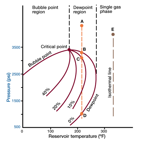
Figure 1 shows a pressure-temperature phase diagram.

The figure shows that if the reservoir pressure and temperature are such as to place the reservoir in the single-phase gas region (Point E), the reservoir fluids will remain single-phase as the reservoir is depleted isothermally. This is so because the isothermal line will never cross the two-phase region. If we consider a reservoir at point A, the reservoir fluid is single-phase. However, as the pressure declines, a point B is reached at which the first drop of liquid appears. Liquid saturation increases as the pressure declines, until it reaches a maximum of over 10%. Upon further decline in pressure this process is reversed, and if point D is achieved all the liquid disappears. This reversal of typical behavior, condensation of fluids as the pressure declines, gives rise to the term retrograde condensation.
Retrograde condensation may result in a considerable loss of valuable hydrocarbons. For all practical purposes, the condensed liquid phase is lost to production. Its volume is very seldom large enough to form a saturation above the critical value required for liquid flow. Thus, as the pressure falls below the dewpoint value, the gas produced is progressively deficient in recoverable liquid content. Because of this, care should always be exercised to maintain the pressure of such reservoirs above the dewpoint value.
The compressibility factor, z, can be determined from pseudore duced pressure and temperature correlations. This requires the availability of proper correlations representing relatively large portions of high molecular weight components in the mixture. Eilert et al. (1957) provides correlations of the pseu docritical values and molecular weight of C7+ fractions. For lean condensates, formation-volume factors used for natural gases may be used to obtain good approximations. For rich condensate systems, such approximations are not adequate. Formation-volume factors should be obtained from laboratory measurements.
A highly important property of a condensate system in any enhanced process employed to recover such fluids is miscibility. (Miscibility exists when two fluids are able to mix in all proportion without any interface forming between them.) In general, a condensate reservoir gas is miscible with any dry hydrocarbon gas. For systems near the dewpoint, miscibility should be determined by laboratory measurements made with a high degree of accuracy in order to define the phase behavior in the region of interest. (Miscibility will be covered in the module dealing with miscible EOR processes.)
Calculations of Initial Gas and Condensate in Place
Calculations of initial gas and condensate in place require the use of the real gas equation of state, with some modifications. First we calculate volumetrically the volume of gas condensate per volume of reservoir:
![]() ……….. (28)
……….. (28)
where:
379.4= volume of one mole, ![]() .
.
G= gas condensate volume, ![]() .
.
![]() = reservoir pressure, psia.
= reservoir pressure, psia.
V= gas volume per reservoir volume, ![]() .
.
z= the gas deviation factor.
R= the gas constant ![]() .
.
TR= reservoir temperature, (∘R).
From the produced surface gas-oil ratio, Rs (scf of dry gas per bbl of condensate), we calculate the number of moles of gas and condensate by
![]()
and
![]() ……….. (29)
……….. (29)
where:
ng= mole of produced gas per bbl of produced liquid.
n0= moles of condensate in one bbl.
ρ0= density of condensate, ![]() .
.
Mo= molecular weight of condensate, lb-mole.
The fraction of gas in the condensate under reservoir conditions is
![]()
 ……….. (30)
The volume of the gas in place per acre–ft is
![]() ……….. (31)
……….. (31)
and the initial distillate in place = ![]() ……….. (32)
……….. (32)
The molecular weight of the tank oil (Mo), if not known, may be estimated by using the following formula developed by Cragoe (1929):
![]() ……….. (33)
……….. (33)
where ![]() is the oil-specific gravity.
is the oil-specific gravity.
The above calculations are illustrated in Example 1.
Example 1
Given:
Reservoir pressure = 2700 psia
Reservoir temperature = 200°F
Porosity = 0.20 Interstitial water saturation = 0.15
Oil gravity at 60°F – 45°API
Daily stock tank oil = 200 bbl
Daily separator gas = 3000 MSCF
Daily stock tank gas = 100 MSCF
The gas deviation factor at reservoir conditions z = 0.8
calculate the initial gas and distillate in place per acre-ft
![]()
Hydrocarbon pore volume, ![]()
Hydrocarbon pore volume, ![]()
![]()
(from Equation 28)
![]() (from Equation 33)
(from Equation 33)
![]()
![]()
 (from Equation 30)
Volume of gas ![]()
Volume of condesate ![]()
In other words, each acre foot of reservoir contains 1339 MSCF of gas, of which 96% will be produced as gas at the surface, and the remainder of which will be liquid condensate at the surface.
As long as the gas condensate fluid remains as single-phase gas in the reservoir, its performance may be calculated as described previously. However, when reservoir temperature and pressure conditions are such as to place the gas in the two-phase region, a liquid phase will develop when the pressure falls below the dewpoint value (retrograde condensation). Prediction of performance then becomes complex.
Retrograde Gas Condensate Reservoirs
Performance One way of predicting the performance is to simulate the reservoir depletion by a laboratory study. A representative fluid sample is placed in a high pressure cell at reservoir pressure and temperature. The pressure is then decreased by “producing” the cell, simulating reservoir depletion. The volume of the cell is kept constant, simulating the constant pore volume of the reservoir. The pressure decrease is achieved by removing incremental amounts of gas. The condensate phase is not removed because it normally forms an immobile phase in the reservoir. Measured liquid recovery from an analysis of the removed gas volumes gives the expected liquids recovery under depletion.
Another way of calculating performance is by use of equilibrium ratios. An equilibrium ratio, K, is the ratio of the mole fraction of any hydrocarbon component in the gas phase to the mole fraction of the same component in the liquid phase. Equilibrium ratios are functions of pressure and composition, and therefore they are not easy to define for complex multicomponent retrograde systems. When K values are available from a laboratory analysis, the engineer can calculate the distribution of any component in the gas and liquid phases as a function of pressure and temperature.
Modern methods of reservoir engineering rely on compositional reservoir simulators to predict performance. These models use an equation of state to calculate phase behavior.
 Petro Shine The Place for Oil and Gas Professionals.


