Related Articles


Communication of Target Changes at the Wellsite
One of the most important aspects of geosteering is communication of target changes to the wellsite personnel. The method used to convey target changes can make the difference as to how much of the well stays in the target. Communication of a steering decision must satisfy four criteria.
- The target change must be possible. Know what the Directional Driller can and cannot do with the BHA that is presently in the hole. Know enough about how a steering correction is made. When in doubt, discuss the target options with the Directional Driller.
- Communication of the target change must be simple. Though the interpretation required to arrive at a decision to change targets may be quite complex, the communication of where to go from here should be simple and concise.
- Target Changes must be quantitative. The Directional Driller is more comfortable with numbers to work with, rather than subjective suggestions about where to put the bit.
- Above all, target changes must be based upon observed geology of the target. The only reason to change the target is because of changes in the geology.
Several methods for managing and communicating target change are found in use today.
Follow the Plan Method
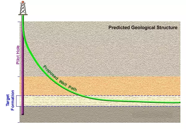
The method that was used when horizontal wells first began was the Follow the Plan method. No geosteering is required for this method, because the pre-drill plan is simply followed to the letter regardless of the geology. Where this method has been used it is quite often found later that the well was not in the intended target for much of the time (Figure 1: A poor targeting technique).
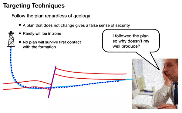
Wells drilled by this method often can be considered an expensive pilot hole that may be re-entered later. This method meets the first three criteria above, but fails miserably with the fourth.
Panic Method
This method is the method of choice for many novice Geosteering team members. When the Geosteering Team gets “lost” then the Geologist makes the best guess and goes searching for the target -either up-section or down-section. This generally occurs out of a lack of knowledge or blind panic. This method does not meet any of the four criteria outlined above, and can be very frustrating to everyone involved with the project (Figure 2).
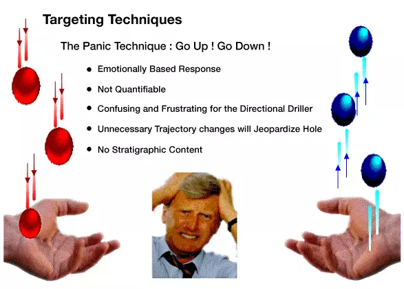
Eventually, the Directional Driller will be less responsive to directions after first going up -then down, looking for the target. Panic will also stand a good chance of endangering the wellbore by creating unnecessary doglegs in the well.
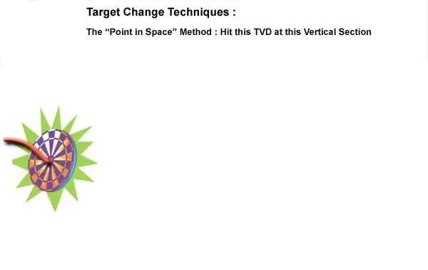
Point in Space Method
The Point in Space method states that the well should be at a target TVD at a certain vertical section or X/Y coordinate. On the surface, this seems like it may be a good method, however when it is examined closely, several flaws are exposed. When specifying a point in space for the Directional Driller to hit, it is often likely that target will be unreachable. By the time that data is interpreted, a decision is made, and the target change is communicated, a good deal of additional hole may have been drilled, thus leaving less room to make the target change.
There can be confusion with this method because the reference is always changing (Figure 3).
Once the point is hit (unless a series of points are given), the driller will be looking for another TVD target. This causes more work for the Geosteering Team than is necessary, because they continually need to give new TVD targets to the Directional Driller.
While the target change information is quantitative, it is not complete. The horizontal well is a line – not a point, so if a target TVD is given without an inclination, the target is incomplete.
While a TVD target in front of the bit may be based upon a projection of the geology, without the corresponding formation dip, a TVD target WILL cause over-steering.
KB TVD or Centerline Method
The KBTVD method states that the well should land on a line defined by a point at a common reference and wellbore inclination. Targets should always be lines -never points. With this method, the position of the drillstring at the last survey and the known stratigraphic position can be used to calculate a new target line that transitions the well to the preferred stratigraphic position. A target line will also give the Directional Driller more flexibility to hit the target without jeopardizing the wellbore plan (Figure 4: The KBTVD Method).
A common reference for depth will simplify the target so that whenever a depth and inclination are given to the Directional Driller, he will know how to define his line to the new target. One method to standardize reporting is to report a depth at zero vertical section (which has been back-calculated from the last survey data) with a wellbore inclination. This depth at 0 vertical section is called KBTVD (Figure 5).
The following formulas can be used to calculate the KBTVD from the last survey and TSP (Figure 6)


Where:


This method may seem complicated, but in reality it makes Geosteering simpler because the reference for the depth that defines the line is always the same.
Target at Last Survey Method
For cases where the azimuth changes radically, an alternate method can be used, called the “Target At Last Survey” method. Here, the TVDnt (New target TVD, see formula above) at the last survey point is calculated and communicated along with a wellbore inclination to the Directional Driller. The Directional Driller can then determine how best to get to the line. While this method works as well, the process seems to go smoother using the KBTVD method.
Target Tolerance
An important addition to the target data is the target tolerance. The target tolerance defines the amount of distance above or below (or from side to side) that the bit is allowed to deviate from the target line. The Directional Driller will then have all of the information required to stay within the target until the geology changes. An example of a typical target to the Directional Driller is typically presented in this format:
KBTVD of 3200 m @ 0 VS with inclination of 93 degrees.
Stay within 4 m above or below the line and 100 feet to either side of the line.
(This gives the driller a window within which to keep the bit.)