Related Articles


Gasified Liquids, Hole Cleaning Considerations
Gasified liquid drilling does not have a specific liquid-volume fraction requirement for good hole cleaning.
It is possible to increase the bottomhole pressure by reducing the gas injection rate or by increasing the liquid rate without affecting the gas consumption. Normally, when drilling with gasified liquids a back-pressure should not be imposed on the annulus. Saponja (1995) presented some annulus pressure readings collected during a gasified drilling operation (Figure 1 Comparison of downhole and surface pressure, Sponja, 1995).
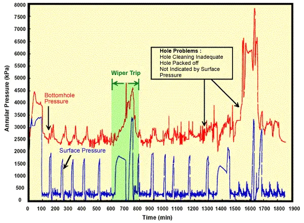
A pressure range of 300-450 psi shows normal drilling conditions, whereas pressures over 850 psi indicates inadequate hole cleaning. On the other hand, the standpipe pressure data might be misleading, since it does not show any indication of a cleaning problem.
Annular velocities of 100 to 200 feet per minute typically are sufficient to keep the hole clean with un-viscosified liquids. Since it is difficult to generate higher annular velocities in large diameter holes, the base liquid viscosity needs to be increased to establish additional cuttings transport capacity.
Settling Velocity
Assuming average flow properties in a gasified liquid mixture, the settling velocity is given by:
Equation 1

where:
vt = particle settling velocity, ft/min
dc = particle diameter, in
ρc = cuttings density, ppg
ρf = average drilling fluid density, ppg
The above equation by Moore (1974) assumes a drag coefficient of 1.5. The annular velocity should exceed vt for the cuttings to move uphole.
According to Guo et al. (1993), the cuttings travel can be calculated as:
Equation 2

The main assumption behind this equation is that the cuttings concentration in the annulus should not exceed some critical value Cc if the hole is to be cleaned.
Thus, in a vertical well, the minimum annular velocity needs to be:
Equation 3

Obviously large cuttings and circulating fluid densities as well as deviated and horizontal wells, require higher annular velocities.
Formation fluid inflow can improve the efficiency of cuttings transport. If the inflow is gas at the bit, it always improves the cleaning performance. However, depending on the depth of inflow with respect to the bit, it may lead to different effects.
Liquid inflow always increases the bottomhole pressure and reduces the efficiency of cuttings transport. We have to keep in mind that all the above discussion about cuttings transport analysis assumes that turbulent flow conditions exist in the wellbore. In the case of a large annulus, the circulating fluid viscosity has to be increased in order to reduce the particle settling velocity, which is defined as:
Equation 4

where:
vt = terminal velocity, ft/min
dc = average particle diameter, in
ρc = cuttings density, ppg
ρf = average drilling fluid density, ppg
μ = effective fluid viscosity, cp
