Related Articles


Logging While Drilling Tools
Horizontal drilling technology has come a long way since the mid-1980’s. With the advent of Measurement While Drilling (MWD) and Logging While Drilling (LWD) tools in the early 1990’s, it was discovered that drill cuttings and drilling parameters alone were often insufficient to keep a well inside its targeted zone. Through the early 1990’s, the choice of MWD tools was limited to basic gamma ray and resistivity tools. These relatively simple tools have proven sufficient in most cases for steering a high-angle well, but tend to fall short of providing a full reservoir evaluation.
As more and more formation evaluation tools were added to the suite, they became known as LWD tools, while directional tools retained the designation of MWD tools.
By the mid-1990’s, the LWD suite included neutron and density tools, and later included a sonic capability. By the end of the 1990’s, MRI tools were being developed for the LWD arena. Such advances in LWD technology enabled a more complete evaluation of the reservoir, nearly on par with -and sometimes even surpassing -the traditional suite of wireline tools.
Because the Gamma Ray measurement is relatively unaffected by formation fluids such as water, oil, and gas, it makes an excellent correlation tool for geonavigation. For this reason, the GR tool is often used as the sole correlation tool. However, because high-angle, extended-reach holes are difficult to log with conventional wireline tools, it is not uncommon for any of a range of LWD tools to be run in the hole as well.
The wide array of formation evaluation LWD tools not only allow horizontal wells to be steered more accurately, but save costs when compared to running “TLC” (tough logging conditions) open hole logs. Evaluation of the real-time data from a horizontal well is a key component of geonavigation, and is the best information for stratigraphic correlation.
Circumferential versus Azimuthal Tools
LWD tools can be subdivided into two main groups, based upon the kind of information that is recorded and the complexity of the tool.
- Circumferential tools record measurements from 360 degrees around the hole. These tools are used for reservoir evaluation and correlation.
- Azimuthal tools measure the formation in a preferred direction (usually up and down) and can be used to detect bed boundaries and determine whether the drillstring is moving up or down through the section. A small population of these tools can further be classified into the subset of Imaging Tools, which can be used to measure formation dip rates and to “see” faults, fractures, and stratigraphic anomalies.
Each of these types of tools will be discussed in turn, below.
Circumferential Tools
Among the circumferential tools, the most common are the gamma ray, resistivity, neutron/density, and sonic devices.
Gamma Ray LWD
The most basic of LWD tools is the circumferential gamma ray tool. These tools are primarily used for correlation and reservoir evaluation. Among the LWD suite of logging tools, the gamma ray has been in use for the longest time; these tools are the most dependable and the least expensive of the LWD suite.
The gamma ray, despite the minimal cost, is the best tool to use for correlation. There are several reasons for this.
- The gamma ray log is primarily a measure of clay content in the rock, and is thus relatively unaffected by fluid saturation and porosity variation through the reservoir. As a result, it has a more consistent character throughout the reservoir.
- The gamma ray in a horizontal well can be used to correlate across facies changes because the hydrodynamic conditions during deposition often follow the same pattern in a sand body and the adjacent shale or siltstone, i.e. coarsening upward or fining upward.
- The gamma ray records accurate placement of the well in-section because of its short depth of investigation.
- Gamma ray tools in horizontal wells can resolve much finer stratigraphy than can be seen in the gamma ray log from vertical wells for two reasons.
- The horizontal wellbore is at a very high angle of attack relative to the beds. (For instance, a 6-inch bed will be traversed by the wellbore in nine feet when the well is within 1 degree of formation dip, thus making it visible to the gamma ray tool.)
- The resolution is further enhanced by slow recording speed. The gamma ray measurement is statistical. If a gamma tool is kept stationary, the sensor will record gamma ray readings that may only vary + 20 units. These readings must be averaged to attain an accurate gamma ray value. While a vertical well may log up through the section at 3000 feet per hour (allowing perhaps only one gamma reading across a thin bed), the average horizontal well is logged much slower (on the order of only several feet per hour). This slow penetration allows for more points to be averaged and a more accurate gamma ray reading to be measured (Figure 1: GR sampling rate of LWD tools is much greater than that of wireline tools).

- The final reason is dependability of the tool. The gamma ray tool has been shown to work under almost every conceivable borehole condition.
Resistivity LWD
LWD Resistivity is critical for meaningful reservoir evaluation, and is especially helpful when drilling in a reservoir with a water contact or gas cap. It can also be used for correlation, provided that such an exercise is carried out with caution.
The resistivity tool is certainly not the best one to use for correlation, because it is greatly affected by fluid saturation and porosity variation throughout the reservoir. The deep-reading tool may even average the bed above and below the bed that the tool is currently in. The shallow resistivity curve can be influenced significantly by borehole effects that can only partially be factored out. The resistivity tool’s effective use for correlation should generally be limited to tight reservoirs with little porosity or fluid saturation variation.
One other aspect of the resistivity reading is the formation of “horns” at thin bed boundaries. These horns are fairly well understood and can generally be filtered or ignored by the interpreter, though they can often be used effectively to pick bed boundaries more precisely.
The most important use of the resistivity LWD for GeoSteering is its ability to “see” fluid contacts before they are penetrated by the wellbore. The deep induction curve looks 4-6 feet into the formation, and should see an approaching oil / water contact before the bit enters the water leg, thus alerting the GeoSteering team to steer the bit away from the troublesome water zone.
The deep-reading resistivity can also be used to identify approaching beds -often well before the bit will see them. However, as the resistivity tool approaches a boundary, it will begin to average the resistivity of the adjacent bed with the readings of the bed enclosing the tool, therefore, formation boundaries with this tool may appear to be very gradational. The ability to detect a bed boundary with resistivity requires a significant contrast between bed resistivity; otherwise the averaging affect reduces the ability to distinguish between variation within a bed and an actual bed boundary.
An additional benefit of running resistivity LWD tools stems from the fact that they will be able to provide the earliest resistivity measurement of the formation, possibly before deep invasion by the drilling fluid sets in. This may be the only opportunity to log the zone before it is invaded.
Figure 2 (LWD measurements are influenced by tool orientation with respect to bit and formation dip, and formation boundaries) illustrates how the resistivity LWD tool, even at a typical position in the BHA (30 to 40 feet behind the bit), can often see approaching beds before the bit arrives.
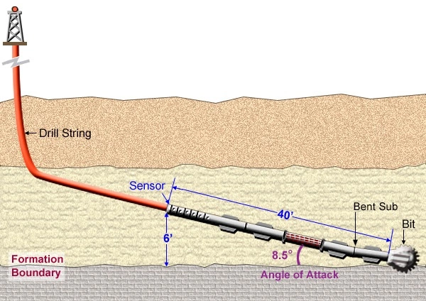
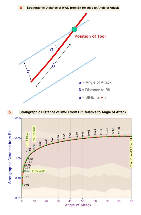
The resistivity device cannot see in front of the tool, only around the tool. If the deep resistivity sensor is 40 feet behind the bit, and the deep resistivity is reading 6 feet into the formation, then the resistivity tool will look at bed boundaries or contacts that the bit has not yet reached for any angle of attack to the formation that is less than 8.5 degrees (Figure 3 a-b).
Density / Neutron LWD
Density / Neutron porosity measurements are essential for petrophysical analysis of a reservoir, and are recommended when drilling above oil / water contacts. When formation porosity must be known for accurate reservoir evaluation, the Density LWD, though not inexpensive, will still save money, as compared to wireline logging after drilling, which will require a drill pipe-conveyed logging system. Furthermore, the density information acquired while drilling can often be useful to geosteer the well into the “sweet spot” of the target.
The Density / Neutron LWD tool, like its wireline equivalent, is a contact tool that has an ultra short depth of investigation (± 6 inches). The tool can be greatly affected by rugose boreholes because the tool may lose contact with the borehole wall. Contact with the formation can be achieved by placing the sensors within a stabilizer fin of the LWD tool. However, the stabilizer can affect the building properties of the BHA, and this factor should be considered when using the density LWD. The density measurement also requires correction for borehole fluid and hole size. This can sometimes adversely affect the readings. The calibration of the neutron tool, in some cases, may drift. The effect worsens the longer the tool is in the hole, so the neutron values should be used as a relative measure rather than an absolute measure of porosity.
Because of the short depth of investigation, the density tool can be used effectively for correlation in many formations. However, in a reservoir with variable porosity it is best to use the gamma ray as the primary correlation tool, while using the density data to identify or verify porosity variation through the reservoir. The short depth of investigation can also be used to accurately pick bed boundaries.
The density tool, in conjunction with the resistivity tool, can be effective when trying to maintain position above an oil / water contact by using calculations of water saturation (Sw) to estimate height above the contact. This can be especially helpful where a gradational contact is present.
Sonic LWD
The sonic tool is fairly new to the LWD suite, but promises to be a valuable addition. The sonic tool can be used for more accurate time to depth correction to seismic, porosity determination, determination of rock mechanics, and to detect beds at a significant distance from the wellbore.
Early LWD sonic tools were not as dependable as the latest generation of tools. A high tool failure rate and the inability to adequately deal with bit and pipe noise meant that the tool was very rarely used. New methods for filtering out extraneous noise and more robust tool designs are making the LWD sonic a much more useful tool.
As in vertical holes, the sonic porosity measurements are not as favored as density logs for porosity measurements, but may be the tool of choice in certain instances. The sonic tool is the best choice for porosity measurement in areas where there is a problem with hole rugosity, when it is not advisable to have a radioactive source in the hole, when a “slick” bottom hole assembly is required, or when the sonic is also required for seismic time to depth conversion.
The LWD sonic is used primarily to obtain more accurate time-to-depth corrections to seismic as the well is drilling. The operator should be cautioned that a synthetic seismogram of a measured depth sonic log is quite useless in a horizontal wellbore. The data must first be converted to true stratigraphic position (TSP) before a synthetic seismogram can be useful. This means that the distortions caused in the measured depth log by the interaction of formation dip, faults and wellbore geometry must be removed to restore the data to its proper place within the stratigraphic section. Only after these steps are taken can an accurate correlation to seismic be made.
Because it is a deep-reading device, the sonic tool can be used to detect formation boundaries before they are penetrated by the wellbore.
Ultrasonic Calipers
On LWD tools, ultrasonic calipers are used primarily as a way of measuring borehole size and standoff, in order to compensate the porosity measurements for inconsistent contact. Typically, 3 acoustic transducers are placed next to the density segment of the LWD tool string and spaced at 120-degree intervals. These calipers provide greater coverage of the borehole than most wireline tools are capable of, with several measurements obtained over the course of a single revolution. (For example, when rotating at 200 RPM, the Baker Hughes INTEQ tool makes 200 such measurements per second -1 measurement every 6 degrees.) In addition to compensating the density measurement for borehole rugosity, lateral tool vibration, and tool eccentricity, the calipers can also be used to determine hole shape, as well as hole volume and cement volume.
Azimuthal Tools
An azimuthal tool is an LWD tool that has the ability to record measurements from a focused direction relative to the wellbore. There are two ways to accomplish this. Preferably, it is best to have the ability to “see” the top side of the hole and the bottom side of the hole so that a comparison can be made between the two readings. There are two categories of LWD azimuthal tools.
- The first group of tools uses diametrically opposed sensors. For these tools, the azimuthal readings can only be recorded when the drillstring is not rotating. These tools usually require the well to “ream-log” each stand with the drillstring oriented to insure that the tool is looking up and down. Ream-logging is carried out by pulling the current stand off bottom, after which the drill string is oriented and then slowly and steadily lowered back to bottom. This method requires additional rig time and may introduce uncertainty in the readings if the orientation is not maintained while the drillstring is lowered to bottom.
- The second group of tools has a focused sensor with electronics that keep track of the relative position of the sensor. The drawback of this tool is that it only works in rotating mode, so the hole must be ream-logged, with the drillstring rotating, across any intervals where the drillstring had previously been kept stationary to slide for inclination or azimuth correction. This means that such tools must be ream-logged through the build section, but in the lateral must be ream-logged only in slide intervals. This method requires less ream-logging than the dual sensor system.
Most LWD contractors can provide only one method or the other, so if azimuthal tools are required, it is advisable to find out which method is used by one’s contractor of choice.
Azimuthal Gamma Ray
The azimuthal gamma ray can be used to determine whether the well is traversing down stratigraphic section or up stratigraphic section. In addition, the tool can detect bed boundaries; however, because of its shallow depth of investigation, this role is limited. Most gamma ray tools see only 6 -12 inches into the formation. This does not generally give an operator enough warning to make a correction before the well will drill through the bed boundary. The azimuthal sensors for gamma ray cannot be precisely focused, so a fairly broad wedge of formation (30 to 45 degrees) is averaged into the readings.
Azimuthal Resistivity
Resistivity is one of the most useful tools in an azimuthal mode for two reasons.
- The resistivity tool is focused at several depths of investigation. This makes bed detection more precise because the deep-reading curves will see the bed first, and each successive resistivity curve will see it a little later. A subjective estimate of the angle of attack of the wellbore to the formation can be seen. If the deep reading tools and the shallow reading tools see a bed boundary in quick succession, then it can be surmised that the well is going through section at a relatively high angle. The first detection profile spreads out as the well gets closer and closer to formation dip.
- As with the gamma ray, by comparing the top of hole data to the bottom of hole data, the direction of traverse through the stratigraphic section can usually be determined.
The deep resistivity, because of its depth of investigation, may experience problems of bed confusion when drilling through thin beds. In this case, it will not always be obvious which bed the deep-reading resistivity is seeing.
Resistivity Imaging
A resistivity imaging tool is available for LWD applications, but it is run directly behind the bit. Such placement precludes the use of a mud motor, and thus prevents its use in any part of the wellbore where a mud motor would be used.
An example of such a tool is the Schlumberger RAB (resistivity at the bit) tool, which has depths of investigation set at 1-3- and 5 inches. This is a laterolog type of resistivity tool, and will not work in oil-based or other non-conductive muds.
Azimuthal Density
The density tool is naturally azimuthal in nature, because it is a contact tool and so sees only data from the specific segment of the hole that the sensor is touching. A very valuable tool is created when electronics are added to keep track of the sensor position relative to the top side of the borehole.
Density Imaging
The azimuthal nature of the density tool and its ultra-shallow depth of investigation can be used to advantage for providing density images. These images are similar to images produced with a Formation Micro Imager (FMI) resistivity tool, except that they are obtained in real-time. The resolution of density images is much coarser than the FMI images (one to two inches), but nonetheless often provides enough data to detect bed boundaries and allow the operator to determine true formation dip.
Density imaging is the only method available that provides true formation dip. The operator should be cautioned that when using dips from images for geosteering, the apparent dips should be calculated using the azimuth of the wellbore, the inclination will not be at the anticipated angle of attack.
Azimuthal Data Interpretation: Traversing Through a Section
One of the primary uses of any azimuthal tool is to determine whether the well is traversing down through section or up through section. Figure 5 (Traversing up and down a section) illustrates how any azimuthal tool can show the direction of traverse.
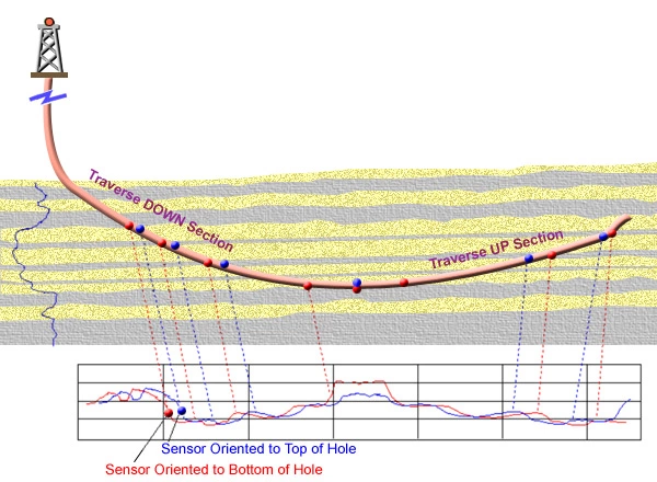
When traversing down section, the sensor directed toward the bottom of hole detects bed boundaries first. These same bed boundaries will be seen subsequently by the sensor directed toward the top of hole. The order of detection reverses when the well is traversing back up the section. Though such tracking is readily seen in this simple example, in actual practice, it is more difficult to determine which sensor is seeing a bed first, especially in complex structures.
Prioritizing LWD Data
The information presented to the GeoSteering Team can at times be overwhelming, so it is important to prioritize and compartmentalize the wellbore information into geonavigation information and formation evaluation information. Geosteering decisions often require a quick response, and trying to wade through data that does not truly affect the steering decision will interfere with the decision-making process.
Before kicking off a horizontal well, the geoscientist must separate the data that must be known for geosteering from that which must be known for a complete reservoir evaluation. The reservoir evaluation can wait until after the steering decision is made:
First interpret that data which is most useful for geosteering; then make a full evaluation of the reservoir when not as pressed for time.
LWD tools provide raw data from the wellbore, and this data MUST FIRST BE INTERPRETED BEFORE A DECISION CAN BE MADE. Interpreting horizontal data can be difficult at times, so it is imperative that the proper evaluation methods and interpretive tools be used. Each type of interpretive method has its advantages and pitfalls, both of which must be understood to obtain the full advantage for each method.
