Drill String Design
As inclination angle increases in a directional or horizontal well, the borehole walls support more of the drill string weight. This contact, along with the capstan effect (the normal force caused by the deformation of an axially loaded member about some obstacle), results in frictional forces that oppose the drill string’s rotation and axial movement.
During pipe rotation, frictional loading manifests itself as surface torque above and beyond that applied at the bit. During axial movement, it shows up as a difference in hook load between the indicated drill string weight and the actual vertical component of drill string weight–either as updrag (when pulling out of the hole) or downdrag (when running in the hole).
Buckling occurs when the compressive load in a tubular exceeds a critical value, beyond which the tubular is no longer stable and deforms into a sinusoidal or helical shape. Sinusoidal buckling (first mode of buckling) corresponds to a tube that snaps into a sinusoidal shape. This first mode of buckling is sometimes called lateral buckling, snaking or two-dimensional buckling. Helical buckling (second mode of buckling) corresponds to a tube that snaps into a helical or spiral shape.
Depending on the well profile, torque and drag loads can become significant limiting factors during drilling and casing operations. Factors that affect drill string torque and drag limits are:
- Length of the well’s directionally drilled portion.
- Drill string makeup and buckling tendencies.
- Coefficient of friction.
- Rig limitations.
- Drilling method.
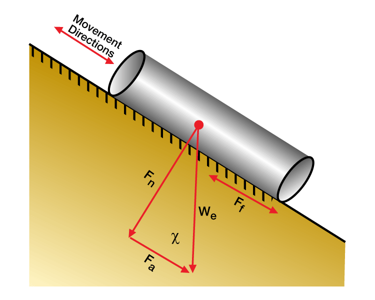
As shown in Figure 1 (Schematic of a drill string section), the components of drill string weight in a wellbore inclined at an angle α from vertical are
![]() (1)
(1)
![]() (2)
(2)
where
Fa, Fn = weight components in axial and normal directions, respectively
We = effective unit weight of string (e.g., lb/ft)
α= hole inclination angle
Critical Helical Buckling Force (Fhel):
- Inclined wells (straight section):
![]() (3)
(3)
where
E = Young’s Modulus
I = Area moment of inertia
r = radial clearance between hole and pipe
- Horizontal wells:
![]() (4)
(4)
- Vertical wells:
![]() (5)
(5)
Updrag/Downdrag Forces on Drill String:
![]() (5)
(5)
Torque on Drill String:
![]()
where
μs = coefficient of sliding friction
μΓ = rotational coefficient of friction
Fn = resultant normal force
ODpipe = pipe outer diameter
In a vertical well, the most basic design rule is to keep the drill pipe in tension, using drill collars and heavy-wall drill pipe in the bottomhole assembly to transmit weight to the bit. For the most part, this is a simple matter of running enough drill collars in the BHA to ensure that the neutral point (i.e., the point at which the drill string goes from being in tension to being in compression) is always below the drill pipe.
The design criteria for a horizontal well are much more complicated. Transmitting bit weight in the hole’s lateral section requires drilling in compression rather than tension. This requires compressive service drill pipe (i.e., the largest diameter of conventional pipe that the rig can handle) in order to minimize buckling tendencies. At the same time, torque and drag must be kept to a minimum.
In the bend section (or sections, depending on the well profile), the pipe must be able to transmit the same axial and torsional loads as does the pipe in the lateral section. At the same time, it must be able to withstand the bending forces resulting from the section’s curvature, and to resist buckling forces.
The vertical portion of the well may contain a weight stack section that provides the necessary bit weight, consisting of drill collars or heavy-wall drill pipe. This section is generally kept out of the hole’s bend portion to minimize torque and drag. The remainder of the vertical portion may consist of conventional drill pipe run in tension.
It is particularly necessary in horizontal wells to consider the length of the section drilled into each bit run. This is because over the course of a bit run, the pipe moves from one hole section to the next–for example, the compressive drill string segment moves through both the vertical and bend sections before it reaches the section for which it was designed. Thus, the drill string make-up dictates the maximum length of the bit run. This is in contrast to a vertical drill string design, in which we lengthen the drill string simply by adding pipe at the surface. The need to consider bit life adds an additional complication to drill string design.
Bit Selection
Fixed cutter and rolling cutter bits are available for a wide range of rock types and operating conditions, and both of these major bit categories are used in directional and horizontal drilling.
In drilling high-angle wells, two bit selection criteria warrant special attention: the higher rotary speeds characteristic of downhole motors, and side-loading stresses. With conventional rolling cutter bits, such conditions can lead to bearing failure and loss of gauge. The advent of hardened sidecutting elements and inserts, along with such innovations as high-strength seals and journal bearings have resulted in rolling cutter bits that are more suitable to directional applications, and which offer distinct advantages in performance and steerability. At the same time, fixed cutter bits continue to be well-suited for drilling long intervals at high rotary speeds.
Bits for Coiled Tubing (CT) Drilling
The bit chosen for coiled tubing (CT) drilling should operate at torque values consistent with the down hole motor at a range of weight-on-bit (WOB) values set between the following two limits (Portman and Short, 2000).
- The bit must operate at a WOB less than that at which the CT begins to lock-up.
- The bit must operate at a WOB greater than half of the drag between CT and completion. These limits can be estimated using tubular mechanics models (He and Hyllingstad, 1995).
Slim hole drilling with CT requires bits for smooth cutting at low torque values and moderate WOB. Depending on CT and completion, the WOB should be in the range of 500 lbf to 10,000 lbf. Tungsten carbide fixed blade cutters are popular for CT drilling. The low rake angle of carbide inserts prevents the bit from taking too big a “bite” under higher WOB. PDC cutters are typically designed to cut in shear, requiring low WOB with good control. To control the depth of cutter penetration, dampeners are inserted to the side of large-size (i.e., greater than 3½” ) PDC bits. Natural diamond cutters have a very smooth cutting action, requiring low torque under a wide range of WOB values. They presents an excellent bit choice when there are uncertainties in rock properties and WOB control, although a lower rate of penetration (ROP) should be expected. Roller Cone Bits do not generally present a good choice in small hole diameters (i.e., less than 4¾”). This is because in the smaller diameters, bearings tend to be weaker and not sealed, with the exception of single-cone bits. Diamond Impregnated Cutters (30 ~ 40 mesh diamond grit held by a tungsten matrix blend) are recommended to grind extremely abrasive targets for smooth, long life drilling, at high-RPM values.
Bit Selection: Examples
Figure 1 shows a case where WOB can be easily controlled between 0 and 6,000 lbf. In this case, bit choice should be driven more by formation properties.
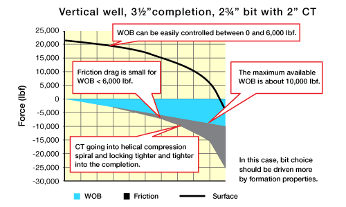
Figure 2 shows a case where a low WOB for a PCD bit could not be controlled due to high friction. In this case, the bit choice should be driven more by high WOB.
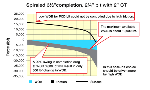
Figure 3 shows a case where drilling with 1,000 lbf to 2,000 lbf WOB generates a stable regime. In this case, a PCD bit is an option.
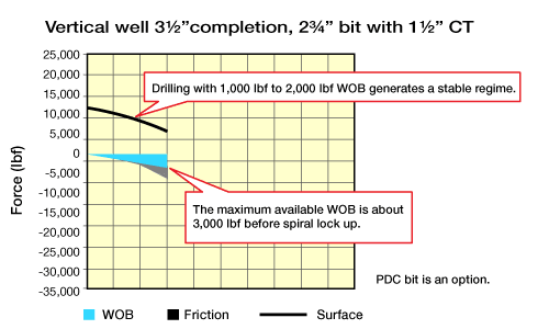
Figure 4 shows a case where the bit must ideally be capable of turning at a WOB of 3,000 lbf to 6,000 lbf for the system to work. In this case, a PDC bit may not be an option.

 Petro Shine The Place for Oil and Gas Professionals.
