Related Articles


Tool Joints
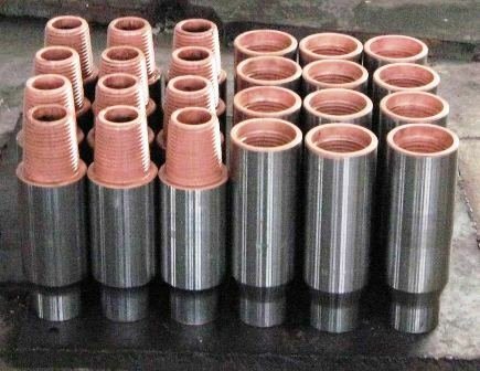
Tool joints (Figure 1) are box-pin connections with rounded threads, which are fabricated separately from the drill pipe tube and then welded on at the upsets.
A key consideration in tool joint design – both from the standpoint of tool joint makeup and rotational forces encountered during drilling – is torsional yield strength. Tool joint performance specifications therefore include information on torsional yield strength and on recommended makeup torque. The proper make-up torque for a tool joint is a function of its type, size, outside diameter, inside diameter and condition.
API Standards for Tool Joints
API RP 7G (1998) and API Spec 7-2/ISO 10424-2 (2008) list standards for various tool joint types, including:
- Internal flush (IF): includes NC26,* NC31, NC38, NC46 and NC50 connections
- Full hole (FH): includes NC40 connections
- Open hole (OH)
- Slim hole (SH): includes NC26, NC31 and NC38 connections
- Slim line (SL): H-90/PAC
- Wide open (WO): includes NC38, NC46 and NC5O connections
- “Xtra” hole (XH): includes NC46 and NC5O connections.
* “NC” designate API Numbered Connection. These API connections were developed for incorporation into the old tool joint connection types, and for design of new connections. The number size is simply the size of the pitch diameter in inches at the gauge point of the threads rounded off to the first two digits with the decimal point removed. For example, the gauge point of the pin in Figure 2, measured 5/8′′ from the shoulder, is 5.616 inches giving a number size of 56.

Table 1 illustrates the differences between some of these basic tool joint types for the case of 4 1/4, 16.60 lb/ft, new Grade 95 drill pipe (API RP 7G).
| Table 1: Properties of New Tool Joints, | ||||||
|---|---|---|---|---|---|---|
| Upset | Tool Joint | OD, inches | ID, inches | Tensile yield, lb | Torsional yield, ft-lb | Recommended make-up torque , ft-lb |
| Internal-External | 6.000 | 3.00 | 976,156 | 34,780 | 21,149 | |
| Internal-External | NC46 | 6.250 | 3.25 | 1,084,426 | 39,659 | 16,997 |
| Internal-External | NC50 | 6.375 | 3.75 | 939,095 | 37,676 | 18,838 |
| Internal-External | 6.000 | 3.25 | 938,984 | 39,021 | 22,616 | |
Tool joints also vary according to the number of threads per inch (ranging between 3 1/2 and 5 threads per inch, with most connections having 4 or 5 threads per inch), the amount of taper per foot and the overall length of the box and pin.
Identification
An examination of the tool joint connections listed above indicates that some of them are identical. For example, the NC 26 connection applies to both Internal Flush and slim hole upsets. This is indeed the case; API RP 7G lists these interchangeable and equivalent connections.
Tool joints are identified by a series of 5 markings stenciled at the base of the pin connection:
- The first marking designates the company symbol.
- The second marking is a number from 1 to 12, indicating the month that the tool joint was welded.
- The third marking denotes the last two digits of the year in which the tool joint was welded (e.g., 06 ⇒ 2006).
- The fourth marking is the pipe mill code.
- The fifth marking is the pipe grade code, designated as follows:
| Grade | Symbol |
|---|---|
| N-80 | N |
| E | E |
| C-75 | C |
| X-95 | X |
| G-105 | G |
| S-135 | S |
| V-150 | V |
| Heavy Wall | Double-stencil pipe grade code |
For example, the markings
ZZ 5 09 I E
at the base of the pin designate the company initials ZZ, and indicate that the tool joint was welded in May 2009 by Nippon Steel Corporation (designation I) on Grade E drill pipe.