Related Articles


Wireline Steering Systems
A wireline steering system consists of a bottomhole assembly that accommodates a measurement probe run on wireline (Figure 1). the probe employs magnetometers to measure direction, and accelerometers to measure hole angle. It also measures the orientation of the tool-face, and other parameters such as time, depth and tool temperature.

The wireline is either run inside the drill-pipe or passed through a side-entry sub, and connected to a surface computer, which processes the information and provides a remote readout. The operator can then correct the tool-face angle as necessary to maintain the well on course.
MWD and LWD Systems
One of the most important advances in modern petroleum technology has been the development of real-time Measurement-While-Drilling (MWD) systems to transmit drilling and directional information, and Logging-While-Drilling (LWD) systems to provide formation evaluation data.
MWD and LWD systems make it possible to monitor and control operations even as drilling is taking place, by allowing operators to:
- Measure drill bit position and trajectory,
- Monitor penetration rate, actual weight-on-bit, downhole torque and drag, vibration and other drilling parameters,
- Compute pore pressures and get an early warning of potential overpressured zones,
- Detect and correlate geologic markers and formation tops,
- Evaluate formations even as they are being drilled.
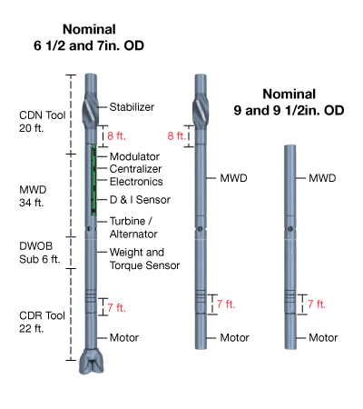
Systems are modular in design, and can be run with various sensor combinations to fit the requirements of the well plan. Figure 1 is a schematic diagram of an MWD/LWD system,

while Figure 2 shows typical system configurations in various bottomhole assemblies.
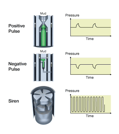
MWD tools operate by creating pressure pulses in the mud column, in response to inputs from the various sensors. Depending on the type of tool, the pulses may be positive, negative or continuous (Figure 3, Mud pulse telemetry). These pulses are converted into electronic signals, which are processed and displayed at the surface.
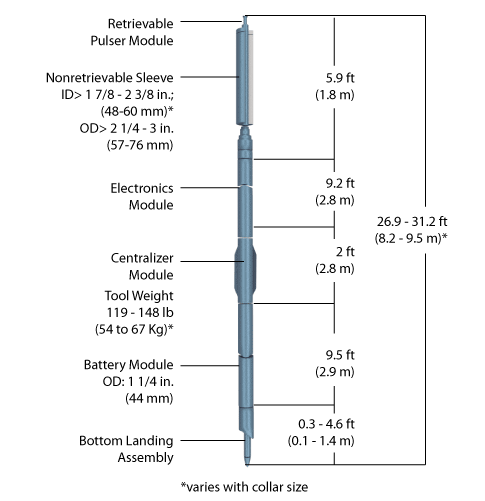
The basic components of the MWD instrument package include:
- a battery-powered pulser module, which in this case employs a continuous mud wave transmission
- a sensor module containing tri-axial inclinometers to measure drift and tri-axial magnetometers to measure azimuth, along with temperature and pressure sensors
- an electronics module.
The MWD tool assembly shown in Figure 4 is run inside standard non-magnetic drill collars.
LWD tools operate on basically the same principles as conventional wireline logging tools. The dual resistivity shown in Figure 5 (Individual MWD and LWD tools) contains a gamma ray tool, and two sets of transmitters and receivers to provide shallow and deep resistivity readings.
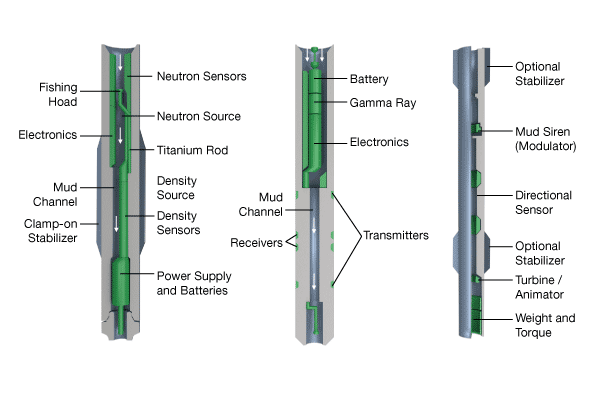
The compensated density-neutron tool measures density and neutron porosity in a manner similar to that of analogous wireline tools.
When drilling with a mud motor, these particular tools are run above the motor assembly–in other words, about 30 or 40 feet above the bit. In some applications, such as drilling in very thin, dipping pay zones, even this small “information gap” between the bit and the tool could lead to problems. For this reason, systems are available that allow “at-the-bit” measurements to be taken within a few feet of bottom.
Although LWD tools work in generally the same manner as conventional logging tools, tool responses will most likely differ between highly deviated wells and vertical wells. These responses require special methods of interpretation.
