Related Articles


Testing Procedures
Testing procedures for the most common cement properties are described here.
- Density
- Thickening time
- Fluid loss
- Rheological
- Set cement strength
- Free fluid and sedimentation
Density
Density is a key factor for oil well cementing. If the cement is too heavy, it can fracture the formation. If it’s too light, the strength will be negatively affected and it may not be able to contain the formation pore pressure. The required cement slurry density is determined by pressure requirements of the well (fracture pressure, pore pressure and drilling mud weight). When the cement slurry density is determined, other required slurry properties are obtained through the use of additives. Slurry density is measured using a pressurized density balance (Figure 1).
Slurry is poured into the cup and a syringe-type plunger is attached to the cap to apply pressure to the slurry and collapse any air bubbles, as would occur downhole. When placed on a fulcrum and balanced, the density reading in  or
or  can be read from the scale. This balance is very similar to the balance used to measure drilling mud weight.

Thickening Time
Insufficient thickening time can result in cement deposits in the casing, tubing, or drill pipe, and can have economically disastrous consequences. Excessively long thickening time necessitates unduly long waiting-on-cement (WOC) time, and in extreme cases of over-retardation can result in cement that never sets.
Thickening time tests determine the time that cement slurry will remain pumpable under downhole conditions and dynamic wellbore conditions of pressure and temperature.
The required thickening time equals:
Cement mix and pump time + displacement time + shutdown time + a safety factor.
Cement jobs can last from less than two hours to more than 12 hours, depending on well depth and other factors. The minimum pump time for most cementing jobs is about 3 hours. The safety factor will vary, increasing with increased job time.
For example, a job that is estimated to take less than two hours for pumping, displacement and shut-down should have a safety factor of 1 hour. A job lasting 8 to 12 hours should have a safety factor of 2 to 3 additional hours. (Note: These are general guidelines and companies may have their own specific policies.)
The slurry sample is evaluated in a pressurized, temperature-controlled consistometer (Figure 2), that measures the consistency of the slurry in a rotating cup at a specified temperature and pressure. There are also portable versions of this device for well locations, and atmospheric-pressure-only versions.

The consistency is measured in Bearden units (Bc), a dimensionless quantity with no direct conversion to common viscosity units such as centipoises. The test ends when the reading reaches 100 Bc. The results of a thickening time test for a slurry at 185 °F and 10,200 psi, where the thickening time was recorded at 7 hours, 13 minutes, and 30 seconds, show that the cement thickens rapidly during the last hour of the test (Figure 3). The slurry in a consistometer cup experiences no fluid loss, so the thickening time measurement is likely to differ from what will occur in the wellbore unless there is an additive for fluid loss control.

Determining the proper temperature and pressure for the thickening time test requires a good understanding of the subsurface conditions of the particular well being cemented. Temperature and pressure have a significant effect on thickening time. The rate at which cement slurry is exposed to temperature and pressure changes will depend not only on the well’s depth and the geothermal gradient, but also the pumping rate and pipe dimensions. API RP 10B provides a set of equations for calculating a customized schedule for a specific cement job.
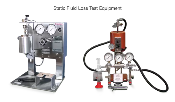
Fluid Loss
A fluid loss test measures the degree of slurry dehydration. After the slurry is mixed and conditioned to expected wellbore conditions, it is placed in a heated cell and subjected to a standard 1,000 psi of differential pressure across a standard set of filter screens of a standard area (3.5  ) for 30 minutes (Figure 4).
There is also a low pressure (100 psi) ambient temperature version of this test that provides less useful information. The reported API fluid loss value is the collected filtrate volume in mL multiplied by a factor of 2. If all of the filtrate collected passes through the filter in less than 30 minutes, an adjusting equation must be used to determine the API fluid loss. The test is performed with the slurry in a static state, although pre-test conditioning may include stirring the slurry in a consistometer or stirred fluid-loss cell. The test is designed to evaluate the slurry under static conditions that occur after the cement has been placed in the well.
High temperature, high pressure systems are available to handle temperatures up to 500 °F and 2,000 psi.
Rheological Measurements
Coaxial cylinder rotational viscometers, (Figure 5), are the most commonly used tools for making rheological (flow property) measurements. After mixing and conditioning a cement slurry in accordance with API RP 10B procedure, the slurry is poured into a pre-heated viscometer cup and dial readings are recorded at various rotational speeds, first in ascending (increasing shear rate) and then in descending (decreasing shear rate) order. Comparing the change in values recorded in each instance indicates whether or not the slurry is shear thinning, that is, exhibiting a stable gelled form at rest but becoming fluid when agitated.

The static gel strength is measured using the same rotational viscometer after the slurry is left undisturbed for 10 seconds and again after resting for 10 minutes. Static gel strength is an important parameter for predicting the capacity of the cement to resist fluid migration between zones in the cement-filled annulus between casing and wellbore.
Other measurement tools rely on acoustic measurements of cement slurry to determine static gel strength under downhole conditions. A static gel strength analyzer, (Figure 6), measures acoustic waveforms transmitted through the cement slurry and transforms those measurements using proprietary algorithms.

Set Cement Strength
Cement strength data is useful for establishing waiting-on-cement time (how long after pumping one must wait before re-starting operations) and monitoring the stability of the set cement. The strength of the cement is determined as a function of curing time through successive measurements.
Compressive strength of set cement samples is tested directly by a destructive crush test or calculated using sonic-velocity measurements. The crush test is carried out on 2-inch cubes of cement that have been cured in a pressurized, temperature controlled curing chamber.
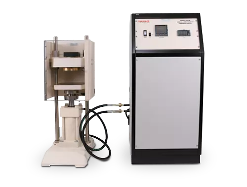
The cubes are placed in a hydraulic press, (Figure 7), where an increasing axial load is exerted until failure. The compressive strength is then calculated by dividing the load at failure by the cross-sectional area of the specimen. API RP 10B provides the prescribed heat up and pressurization schedules which, like the thickening time schedules, are derived from anticipated wellbore temperature gradient. The loading rate in the crush test ( ) is a function of the anticipated strength of the cement.
A strength measurement of 500 psi is adequate for virtually all circumstances. Typically a driller will wait on cement until it has reached a strength level of 100 psi before continuing operations, and 500 psi before drilling out the cemented casing. Achieving ultimate strength is particularly important when setting kick-off plugs when deviating a wellbore.
Strength can also be estimated ultrasonically as a sample of the cement cures, using an ultrasonic cement analyzer,(Figure 8), which measures the travel time of sound waves through the sample.

Sonic strength is correlated to transit time using an empirical relationship. A method has been developed for estimating the strength of a foamed cement using the sonic strength of the base slurry (Cobb 2002).
The strength values obtained in these tests are an indication of the set cement’s competency under uniaxial loading, that is, without any lateral forces restraining the failure. In the actual wellbore situation, the cement will be subjected to triaxial loads and the failure stresses may be substantially different. This test also provides no guide to the shear strength of the casing-to-cement bond or the cement–to-formation bond. More sophisticated tests to determine the strength of set cement include confined triaxial compression tests and a tensile strength test, also known as a “Brazilian” test.
Free Fluid and Sedimentation Tests
Free fluid and slurry sedimentation tests, done at controlled surface conditions of pressure and temperature, measure how slurry density during setting varies with vertical distance due to any tendency to separate into water and particulate phases.
In a free fluid test, a prepared and homogenized slurry sample is poured into a clear graduated cylinder under vibration-free conditions, after which the tube is sealed to prevent evaporation. The total volume of water segregation is measured after a period of two hours.
In a sedimentation test, the cement slurry is poured into a sedimentation tube and then allowed to cure for 24 hours. After the curing period, the cement is removed from the tube and the length of the cement specimen is measured. The sample is then divided into four equal segments, at which time the specific gravity of each segment is measured and the difference between the top and bottom segments is related to the slurry sedimentation (Gandelman et al, 2004).
The cylinders used in these tests can be inclined to simulate deviated or horizontal wellbores.
Other properties
Other slurry or set cement properties that are sometimes measured include:
- Set cement expansion and shrinkage (how much a cement slurry volume expands or shrinks as it sets)
- Gas migration tendency (the ability of cement slurry to prevent gas migration)
- Permeability (the degree to which set cement permits fluids to flow through it)
