Related Articles


Uncertainty Planning
The second phase of pre-drill planning is to determine the range of uncertainty in the geology and the mechanics of drilling, so that contingency plans can be devised. The Geosteering Team should expect that the actual wellbore path will diverge from the optimal plan at some point during the course of drilling.
Statistically, this divergence happens with such frequency as to make its occurrence an absolute certainty. One is simply not looking at all the data, or is ignoring data if the optimal plan always works. Only in rare cases have observed data completely supported the optimal plan.
The only constant in drilling a horizontal well is change. A rigid pre-drill model is doomed to failure. Horizontal drilling often provides a lesson in humility for the GeoSteering team. It can be very frustrating to spend hours developing a pre-drill model, only to have it proven inaccurate before the well is out of the curve. The only way to prevent frustration from leading to poor decisions is to plan for uncertainty.
The plan must anticipate uncertainty in:
- structural and stratigraphic variability,
- mechanical performance of the bottom hole assembly, and
- wellbore position
Each of these problem areas is described below.
Stratigraphic and structural variability
Uncertainty planning exposes the variation that the Geosteering Team may expect to see in a project, both in the stratigraphy and the structure.
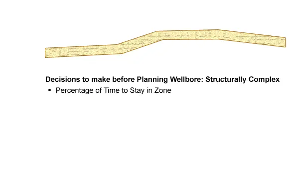
One rule of thumb is that, as the geology becomes more complex:
- the thickness of the target must increase, or
- the percentage of the wellbore exposed to the target must decrease.
Thin reservoirs are most affected by structural and stratigraphic variability. A thin reservoir for this discussion is 15 feet (4.6 meters) or less. “Thin”, however, is a relative term that is related to reservoir thickness versus structural complexity. Some areas have such radical faulting and structure that a 50 foot (15 meter) target may be considered a thin zone for GeoSteering! (See Figure 1)
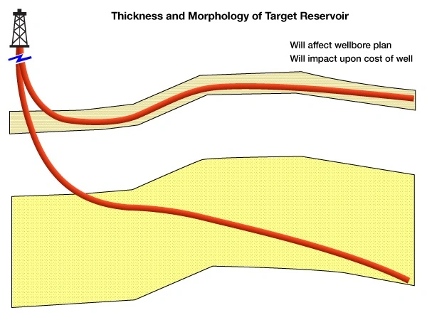
For thin zones in structurally complex areas, there is a trade-off between the amount of wellbore that must be in-zone and the associated cost. Thin zones typically require more course corrections (sliding) than thick zones. The Geosteering Team must expect that if the well absolutely must be in-zone 100% of the time, then drill rate must be controlled and many course corrections will invariably be required. Any course change made to a well will affect total lateral length, so this factor must be taken into consideration.
The Geosteering Team should also map out their options in case the well crosses a fault. The throw of the fault must be determined. A new target across the fault must be acquired, and the GeoSteering team must determine whether the new target is reachable by a simple course correction. The Directional Driller may have difficulty steering the well to the new target if the fault is too big. It is also important to have a bailout contingency to stop drilling in the event that a fault intercepts the lateral section after the wellbore meets most of its main objectives. The other option would be to sidetrack if insufficient exposure to the reservoir has been attained (Figure 2).
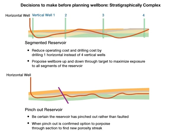
For stratigraphic pinch-outs, a lateral section can be drilled within the pay zone until it can no longer be followed because the zone is either faulted or pinched out. Before proceeding, the Geosteering Team must determine where the well is relative to the target. The well should then be turned in the direction that the reservoir would likely be to confirm the pinch-out. If the reservoir is encountered again, then the “pinch-out” was actually a fault. The well should then be geosteered into the reservoir again. On the other hand, if the well does not encounter the bed after drilling all of the way through the stratigraphic interval where the reservoir was predicted, then the pinch-out is confirmed. Contingency plans should cover the option of continuing the well by undulating up and down through the section until the reservoir is encountered again, or to cease drilling (Figure 3).
Thick reservoirs require a different approach. The configuration of Flow Units within the reservoir will determine how the well is to be drilled. If a thick reservoir consists of just a single flow unit, then the determining factor of wellbore positioning within the reservoir is controlled by the type of drive mechanism in the reservoir. For water-drive reservoirs, the Geosteering Team should endeavor to keep the wellbore as high in the oil column as possible. The lateral section should be optimized between the Gas / Oil and the Oil / Water contacts when a gas cap exists in the reservoir (Figure 4).

For a homogeneous reservoir with a pressure depletion or gravity drainage drive mechanism containing little water, the wellbore is best placed in the bottom of the reservoir with fishhook laterals drilled upward through the reservoir.
Thick reservoirs with multiple Flow Units can be considered as multiple, stacked, thin reservoirs, as seen in Figure 5.
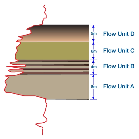
These types of reservoirs are prime candidates for multilateral development. Each Flow Unit should be considered separately as a horizontal target. However, Flow Units that have good lateral permeability can be grouped and drilled with a sinusoidal wellbore to maximize reservoir exposure.
If the structural model is based on seismic interpretation, the Geosteering Team should prepare a Structurally Low Case and a Structurally High Case, based upon the reasonable variation in velocity that may be expected. These two cases will provide a zone in which the target will most likely be encountered. Treat pinch-out edges and facies changes as fuzzy areas, smearing the edges based upon the quality of the data that was used to make the interpretation. Be generous with the size of these areas. The Geosteering Team can overlay these fuzzy areas onto the “Optimal Plan” to predict the areas where steering will most likely be required.
Mechanical Uncertainty
Mechanical uncertainty is manifested in three areas:
- Interaction between the directional BHA and the formation,
- Wellbore position uncertainty due to survey errors, and
- Vertical well spotting errors.
Interaction Between the BHA and the Formation
Every bottom hole assembly (BHA) is affected not only by its mechanical configuration, but by the formation that it is drilling through. The Geosteering Team should expect formation heterogeneity to affect the Build Up Rate (BUR) of the BHA in order to anticipate steering changes. Generally, soft formations cause the BHA to build at a slower rate than hard formations. When building angle through variable stratigraphy, especially in the curve, it is important to watch the build rate carefully to keep the wellbore on track. Hard beds just above the target can be especially hazardous. For instance, the Directional Driller may achieve a consistent BUR, only to have the bit hit a thin hard interval, thus forcing the angle to build much too rapidly and causing the well to lay out above the target.
A hard zone at the top or base of a target can be used to good effect once the well is in the lateral section. These beds often will cause the bit to bounce back into the target as long as the angle of attack is kept below 2 – 4 degrees.
The mud motor and bent sub work in tandem to make directional changes. The directional company has charts which estimate the BUR that a particular configuration of mud motor and bent sub will make. These charts only provide an estimate, however, and actual performance may vary greatly, depending upon the formation that is being drilled (Figure 6).
The best way to reduce the mechanical uncertainty caused by BHA configuration is to find the best Directional Driller with local experience and good references.
The job of the Directional Driller is a combination of skill, intuition, and art. Some Directional Drillers seem to have a magical touch with the BHA and can make it go where they want it to go, while others have difficulties with the simplest of corrections. This can be seen quite often between the day tour and the night tour. The lead Directional Driller often makes higher penetration rates with less sliding. He can often simply change the WOB or ROP to make the bit go where he wants without sliding. This saves time and money. It always pays to check references when choosing a Directional Driller.
Survey Errors
Wellbore position uncertainty due to survey error is perhaps one of the more troubling issues that the GeoSteering team may face. There are four sources of survey errors that must be addressed.
- intrinsic error of measurement in the tools themselves,
- measured depth errors,
- survey calculation errors, and
- improperly positioned surveys
Every measurement of nature contains a certain degree of inherent error because of entropy and because of assumptions made in the calculation of the measurement. The quality of the measuring device can reduce the error but never remove it completely. When a tool is made, it is made with “tolerances”. Error is introduced as a result of these tolerances. When multiple directional measurements are obtained as the well progresses, one error is added to the next. For this reason, wellbore position uncertainty increases with lateral length.
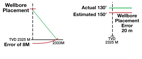
Wellbore position is not measured in a continuous, real-time measurement, but at discrete stations along the well path. It also must be understood that TVD and X -Y position of the well are not measured directly. Only inclination and azimuth at the survey position is measured. TVD and X -Y positions are then calculated from the inclination and azimuth data. MWD inclination measurements are only accurate to within 0.25 to 0.75 degrees. This means that the TVD may be incorrect by two to four feet per thousand feet drilled with well-maintained tools. Errors of more than 14 feet per thousand feet have been documented!
The best way to alleviate TVD uncertainty is to base the wellbore position on stratigraphic position, rather than simply a point in space. After all, a horizontal well is drilled for a particular stratigraphic target that will optimize production from the reservoir. Therefore, it makes sense that the stratigraphy should be the reference for wellbore positioning. If the Geosteering Team knows the stratigraphic position of the well relative to target, then the well will meet its objectives, despite errors in TVD.
Azimuth errors are more pronounced. The primary cause of azimuth error is local fluctuation within the earth’s magnetic field. The magnetic field can vary due to the proximity of ore bodies, basement features, mineralogy surrounding the target and magnetic declination. Azimuthal readings become more problematic with increasing distance North or South from the equator. Azimuthal readings are accurate only to within 0.75 to 2.0 degrees. This can create errors of X and Y of 3 -6 feet per thousand feet drilled (Figure 7: Uncertainty increases with depth, as illustrated by larger and larger ellipses of uncertainty).

Errors that are much higher have been documented near magnetic anomalies.
An inaccurate measured depth to the survey point introduces errors into the survey calculations. Errors of this nature can be attributed to stretch and compression of drill pipe, or even strap-out errors. Most of these errors can be alleviated by using good oil field measurement practices (and careful observation).
Further errors are introduced in the calculations between surveys. Several survey calculation methods are in use, but by far, the Minimum Radius of Curvature method gives the best result. Calculations between directional companies, using the same data set and the same calculation method can produce survey calculations that are different by as much as 0.1 foot per thousand. Assumptions for the value of pi (π) and estimations to avoid division by zero errors provide the greatest source of these variations.
Improper positioning of surveys can create further errors in the calculation. Surveys are generally taken 30 – 90 foot intervals. The survey is calculated by using the change in inclination and azimuth between the two survey points, and then drawing a curve to connect these vector measurements. A Driller can introduce error into the calculation by simply sliding 4 -10 feet to correct his trajectory. Because survey calculations are 30 feet or more apart, the calculation will average the effects of the slide. (Figure 8: Improper survey positioning).

Errors in Well Spotting
Problems with wellbore positioning may result from using offset vertical wells for planning and reference for drilling the horizontal wellbore. Geologists too often assume that the maps used are accurate, and that the vertical logs used for correlation are correct in depth and character (Figure 9: Errors in spotting a vertical wellbore on the prospect map).
This is not always the case. Common errors may occur during the creation of maps, staking of vertical well locations, and measurement of log depths in vertical wells. These errors can cause the geologist to believe a horizontal well is on target when it is not.
A problem typically seen in older wells drilled through steeply dipping formations may occur when a “vertical” well has an unknown or undetected deviation. Errors of this type can cause depths in the well to be off as much as 25 feet. If feasible, it is good to run a directional survey in old wells that will be used as references for steering. At the very least, compare the old wells to a newer TVD log in a well that has directional surveys to determine whether the thickness of formations in the old well has been significantly affected by deviation.
The most common error to occur when calculating the sub-sea depth of a formation pick stems from the use of incorrect ground elevation. The elevations of vertical wells are not always surveyed in to a USGS marker. In the past, it was not uncommon for the elevation on the drilling permit to be estimated from a topographic map, rather than being surveyed in. This has created huge errors in elevation; the largest elevation error documented is 150 meters! Usually the errors are between 5 to 50 feet. (In a horizontal wellbore, where target thickness may only be 20 -50 feet, such an error can doom the well to failure.) To alleviate these errors ALL VERTICAL WELLS TO BE USED FOR GEOSTEERING SHOULD BE SURVEYED RELATIVE TO THE HORIZONTAL WELL.
Another survey problem can be created by using elevation data obtained from a survey that was conducted before the rig moved onto location. Often, the location is surveyed, the site is prepared, and the rig is moved into place on the basis of the survey. A tape measurement is taken from ground level to the rig floor, and this elevation is assumed to represent actual rig floor elevation. However, the site preparation work can often remove a foot or more of soil, and the weight of the rig itself may cause additional settling of the prepared surface. For this reason, the elevation of the rig floor or Kelly bushing should be re-surveyed after the rig has moved onto location.
Mis-spotting vertical wells on the base map is yet another common problem that can be avoided by surveying the location of vertical wells in the vicinity of the proposed horizontal well.
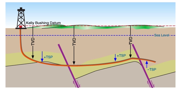
Wellbore positioning errors can be avoided by using the geology revealed in the horizontal well and reference-steering to the stratigraphy by using TSP rather than TVD (Figure 10: TSP versus TVD).
While pre-planning a horizontal wellbore will not make the formation stay where the Geosteering Team would like it to be, it will prepare the Team to make appropriate decisions in a timely manner and without panic when the geology does not match the model.