The Optimal Geosteering Plan
Every horizontal well should be designed to achieve very specific objectives. To meet these objectives, the Geosteering Team must prepare an optimal plan that includes:
- stratigraphic parameters which are well stated and defined.
- structural parameters which are well stated and defined.
- mechanical parameters which are stated concisely and accurately.
The Optimal Geosteering Plan is based on the horizontal well design, and assumes that the well will be drilled in accordance with the above parameters.
Defining Stratigraphic Parameters
The Geosteering Plan should explicitly define the following stratigraphic parameters:
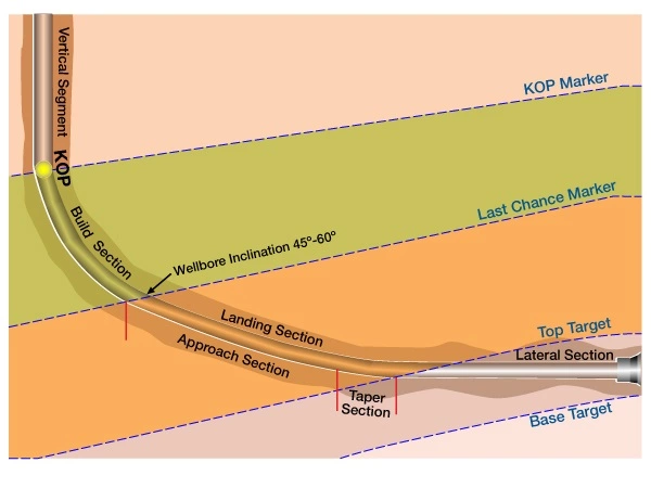
- Stratigraphic marker for Kick Off Point: The stratigraphic marker immediately above the Kick Off Point (KOP) must be identified (Figure 1: KOP Marker).

- The reservoir thickness: An Isopach map for thickness variation within the reservoir should be used to make the best estimate of reservoir thickness.
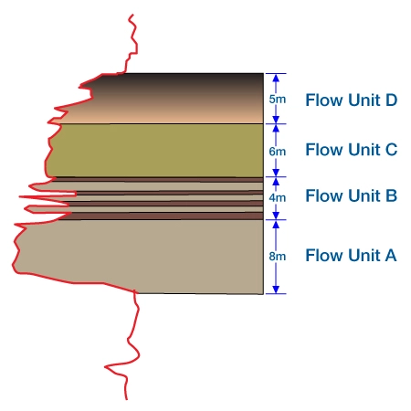
- Determination of Flow Units: When distinctive flow characteristics are recognized within segmented zones of the reservoir, then the reservoir should be subdivided into “flow units” (FU), as shown in Figure 2. Each flow unit should be assigned a priority for penetration.

- Identification of Potential Drilling Hazards: These include fissile shales in the build section or within the target zone, ash beds, expanding clays in the reservoir, salt, or pressure anomalies. In targets when the reservoir rock is hard, trapping zones can create a significant hazard. The Geosteering Team should examine e-logs, core reports, drilling reports and mudlogs from adjacent wells to identify potential drilling problems.Conversely, a hard siltstone, anhydrite, or other hard bed within the reservoir may present an impenetrable barrier if the bit’s angle of attack is less than 2 -4 degrees to the formation. If a hard streak lies at the top of a target interval, the Geosteering Plan should call for the well to be landed in the target at an angle that is high enough to ensure penetration through the zone.
- Lateral Stratigraphic Variation: The lateral stratigraphic variation of the reservoir that falls within the build section should be predicted, based upon available data.
- Identification of the Last Chance Marker: The Last Chance marker is a distinctive stratigraphic marker that can be used to make final adjustments before landing the curve, as shown in Figure 1. This marker should be penetrated with a drillstring inclination of 45 -60 degrees. Distinctive stratigraphy will not always present itself in every well, but when available, the Geosteering Team will be able to tie the marker to the projected target section, and then determine whether the current trajectory will put the well on course for intercepting the target as planned.
- Stratigraphic Center-Line with Tolerances: The Geosteering Team should know where the stratigraphic “sweet-spot” lies, and develop their plan to keep the wellbore within that zone. Tolerances for the target should be defined relative to the Top and the Base of target. A stratigraphic “sweet spot” should be expressed as a certain distance below the top of target, rather than a simple TVD or coordinate in space.
Defining Structural Parameters
The structural parameters should state at the minimum:
- Depth to target at 0 vertical section: (immediately below the rig) and formation dip of target: All targets in a horizontal well should be stated as a depth and dip (or inclination). This will give the Directional Driller flexibility to land the well along a line, rather than a point in space located at some pre-defined TVD.
- Dip Variation / Average Dip: The average dip of the target zone, and of the formations above the target should be determined. Just as important is the variance above and below average dip, which will allow the Geosteering Team to estimate the amount of course correction that may be expected while drilling the well.
- Structural model: A pre-drill model structural model must be created to establish whether all stratigraphic targets can be reasonably penetrated.
- Depth to Gas / Oil / Water contacts: Proximity to contacts is critical for establishing wellbore tolerances within the target zone.
Defining Mechanical Parameters
The mechanical parameters should state at the minimum:
- Minimum and Maximum Lateral exposure to target: The minimum wellbore exposure that optimizes the reservoir performance must be determined. Minimum lateral exposure does not constitute the lateral length of the wellbore, but rather, it defines the length of the segment of the well that is in target.The maximum hole that can be drilled is based upon economics and producibility of the well. It is not always best to “drill as far as we can”. Many reservoirs, especially those with high permeability, will not efficiently produce from the end of a long lateral.
- Build Up Rate for Curve: The best Build Up Rate (BUR) should be based upon the planned length of the lateral section, the type of formation through which the curve will be built, and the completion plan of the wellbore.
Once the basic information has been determined, the “optimal” wellbore should can designed to meet the stated objectives for the least cost. In all probability, this wellbore will not be the one that is actually drilled. The objectives of the project should be set in stone, while the actual path of the wellbore should be set in sand.
 Petro Shine The Place for Oil and Gas Professionals.


