Related Articles


Permeameter Measurements of Permeability
In a core analysis laboratory, the permeability is determined by flowing a fluid of a known viscosity at a specified rate through a core of known length and diameter, and then measuring the resulting pressure drop across the core. For routine core analysis, the fluid used may sometimes be air, but it is more frequently either nitrogen or helium.
Core Plugs
A schematic of the principle involved in the permeability measurement of core plugs using a permeameter is shown in Figure 1.
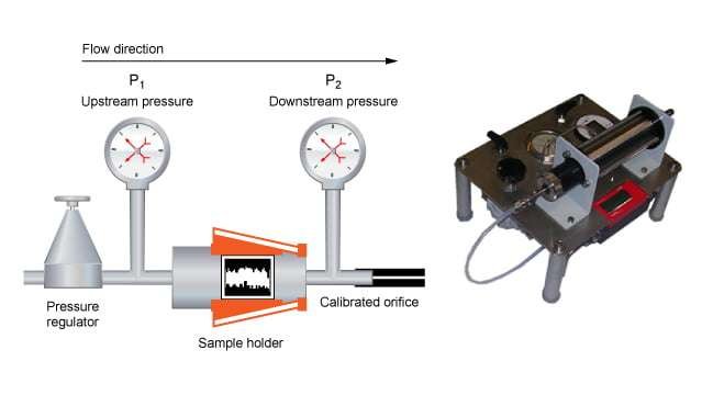
A clean, dry core plug sample is placed in a holder; it must fit tightly and allow no air to by-pass along the sides of the sample. Upstream and downstream pressures are measured to determine the pressure differential across the core sample. As Figure 1 shows, the calibrated orifice allows the flow rate, in cubic centimeters per second, to be measured at atmospheric pressure.
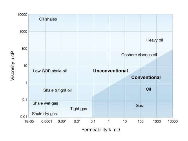
Increased interest in recent years in both conventional and unconventional low permeability reservoirs (Figure 2) has resulted in the development of nonsteady-state permeameters that generate permeability data within an acceptable time period, thus avoiding delays to the analysis and subsequent decision-making using the resultant permeability data. Steady-state is the condition of a system when some or all of the quantities describing it are independent of time, but not necessarily in thermodynamic or chemical equilibrium. The major difference in unsteady state techniques is that saturation equilibrium is not achieved during the test. Additionally, fluids are not injected simultaneously into the core. Instead, the test involves displacing in-situ fluids with a constant gradient driving fluid. The outlet fluid composition and flow rate are measured and used in determining the relative permeability.
The nonsteady-state technique allows the determination of permeabilities to be made in a matter of minutes rather than a full day, as is generally required with steady-state methods. The computation of the air permeability is made as fluid is flowing through the core. This process avoids the requirement for steady-state equilibrium conditions. Hence, low permeability samples may not require long-term testing, an advantage in analysis time and cost, and enabling faster decision-making using the core analysis results.
Full Diameter Cores
Reservoirs normally display some degree of heterogeneity (Figure 3) and, therefore, sidewall core samples alone are often not either sufficiently representative or comprehensive to adequately describe the reservoir’s permeability. Sidewall cores are typically from 1 to 2.5 inches in length, and are acquired at right angles to the wellbore, using well logs to guide their acquisition rather than a careful visual inspection of the physical rock. Full diameter cores are generally from 1.75 inches to 5.25 inches in diameter and often 30 feet or more in length, and thus provide more representative permeability measurements than sidewall core samples.

Full diameter cores also allow the important directional (horizontal and vertical) permeabilities in the reservoir to be determined. It is fairly common to make two horizontal permeability measurements on full diameter core samples. The second measurement is made at right angles to the first. When fractures are visible in the core, the first measurement is usually made parallel to these fractures. The maximum horizontal permeability is recorded as kmax, and the other at 90º to the direction of this flow is termed k90.
The core analyst loads a clean, dry core sample into a core holder, where it is enclosed in a gas-tight elastomer sleeve. The permeameter (Figure 4) forces pressurized gas through the inlet port and into the core. The pressure differential and flow rate are metered at the outlet port. This configuration is used in a steady-state gas permeameter.
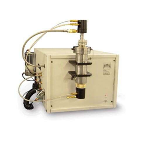
Alternatively, a chamber is charged to a high gas pressure. A valve is opened, enabling the gas to pass through the core plug as the pressure declines. If this unsteady-state, or pressure-transient permeameter, is used, the core analyst can use the time rate of change of pressure and effluent flow rate to determine the core plug permeability.
Vertical permeability on a full diameter core sample is often measured using a Hassler-type core holder, as illustrated in Figure 5. The sample is placed in the apparatus and the rubber tubing is then collapsed around the core. With the introduction of high pressure air, nitrogen or helium to the holder, the tubing provides a seal along the sides of the sample. Low pressure air, nitrogen or helium is introduced on the upstream end of the core and the measurements needed to compute the permeability are easily made.
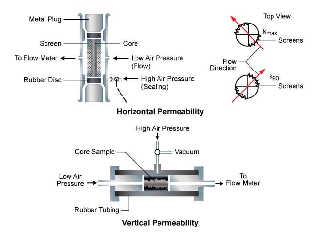
Obtaining full diameter core horizontal permeability measurements is more complex. Screens are placed on opposite sides of the full diameter core and the sample is then moved into the core holder. Non-permeable rubber disks are placed on each end of the sample and the rubber tubing is again collapsed around the core. Low pressure air, nitrogen or helium, is introduced into the center of the holder, passes through the rubber boot, intersects with the screen and flows vertically in the screen. The gas then flows through the full diameter sample along its full length and emerges on the opposite side, where the screen again allows free flow of the gas to the exit port. In this situation, the flow length is a function of the core diameter. The cross-sectional area of flow is a function of the length of the core sample and of the core diameter. The screens are selected to cover designated outer segments of the full diameter sample. In most cases, the circumference of the core is divided into four equal quadrants and the screens occupy two opposite quadrants. In this measurement, a geometric factor, G, is substituted for the shape factor, L/A, in the Darcy equation.
Care must be taken to ensure that the invasion of coring fluid solids during the acquisition of the core does not reduce the permeabilities. This type of reduction can happen in sandstones as well as in chalk limestones. In the latter, ground limestone powder that has been produced by the temperature and pressure conditions encountered while acquiring the core is sometimes plastered on the core, causing a permeability reduction. This powder must be removed prior to full diameter core permeability measurements, as it forms a “skin” that will result in erroneously low permeability values. This material can sometimes be cut away easily when the core is wet; otherwise, sand blasting or rasping of the dry core may be necessary to remove the plaster coat. Figure 6 shows a comparison of actual plug permeabilities with plastered (damaged) full diameter core values.
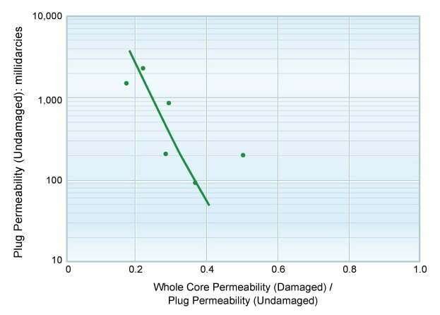
The plugs in this case were cut from the center of the full diameter core, and therefore were not subjected to significant damage. The data indicate that the permeability reduction was greatest for the high permeability section, but all the damaged core permeability values were reduced.
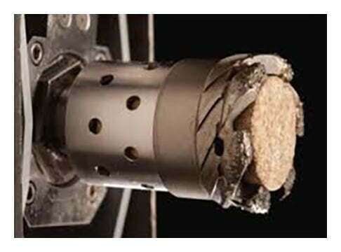
Sidewall Cores
When sidewall core samples (Figure 7) have been mounted in thin-walled jackets in the laboratory analysis procedure, the permeability is determined using techniques similar to those used for normally drilled plugs from full diameter cores. When the sidewall core samples are sufficiently large, which is more often true with rotary than percussion sidewall cores, a portion of the sidewall core is cut from the sample and mounted in a plastic or wax holding material. This mounted sample can then be tested in normal plug equipment.
In some cases, especially with many percussion sidewall core samples, the sidewall sample is so small that the entire recovered sample is used up for the porosity and residual fluid determinations. Where samples are large enough for measurements to be made, experience has shown that the percussion sidewall sample permeability measured in soft rock is often about one third, or even less, of the value that would be determined from a core plug cut from the center of a full diameter core from the same interval. This is caused by both the invasion of the core by drilling mud solids and by the rearrangement of sand grains through percussion at the time the sidewall core is acquired.
Because of these detrimental effects and the need to use all of the sidewall sample for other measurements, if there is no full diameter core available, then permeability values are commonly estimated from previously developed correlations for the same formation in nearby wells. The correlation used usually relates the permeability to the porosity, grain size and distribution and the shaliness of the core. The correlation is developed from those conventional, full diameter cores on which the permeability, porosity, shaliness and grain size distribution have been measured. With the value for these parameters available from cores, an estimation of the permeability of the sidewall core is possible. When the permeability value is estimated, it should be clearly noted on the core analysis report.
The visual estimation of grain size and its distribution, as well as of shaliness, is somewhat subjective. Estimates of permeability can be improved if objective means are used for estimating the average grain size and distribution and the shaliness of the core. Equipment for making these determinations is used in many sidewall core analysis laboratories, allowing the detection of silt-size and smaller particles, including clays.
Measured permeability values for percussion sidewall cores are frequently erroneously lower than those for conventional cores when both are taken from soft sediment. Measured values are often erroneously high in percussion sidewall cores from hard, well-cemented rock, which is shattered by the impact of the bullet used to retrieve the sample.
