ad
Drilling
Trending

Horizontal Drilling | What is a horizontal drilling?

Build Curve Design


There are four basic build curve designs used in bringing a well from vertical to horizontal:

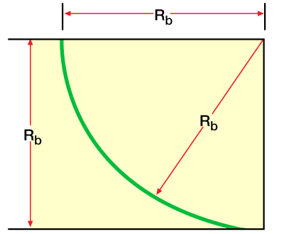
  • single build (Figure 1)
Single build, Build Curve Design, Horizontal Wells, Directional and Horizontal Drilling, Directional Drilling
FIGURE 1
  • simple tangent (Figure 2)
Simple tangent, Build Curve Design, Horizontal Wells, Directional and Horizontal Drilling, Directional Drilling
FIGURE 2
  • Complex tangent (Figure 3)
Complex tangent, Build Curve Design, Horizontal Wells, Directional and Horizontal Drilling, Directional Drilling
FIGURE 3


  • Ideal (Figure 4)
Ideal Build Curve, Build Curve Design, Horizontal Wells, Directional and Horizontal Drilling, Directional Drilling
FIGURE 4

The equations for designing these curve types are easy to derive, and are summarized below (Schuh, 1989).

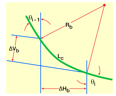
From Figure 5 (Circular arc),

Circular arc build curve design, Build Curve Design, Horizontal Wells, Directional and Horizontal Drilling, Directional Drilling
FIGURE 5

L_{c}= \dfrac{\theta _{i}-\theta _{i-1}}{BR} (1)

\Delta H_{b}= R_{b}\cdot \left ( \cos\theta_{i-1}-\cos \theta_{i} \right ) (2)

\Delta V_{b}= R_{b}\cdot \left ( \sin \theta_{i-1}-\sin \theta_{i} \right ) (3)

where

Lc = length of curved section

Rb = build curve radius

BR = build rate angle

ΔHb = horizontal displacement of build curve section

ΔVb = vertical displacement of build curve section

θiθi−1 = inclination angles at stations i and i−1, respectively, on build curve

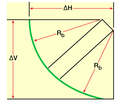
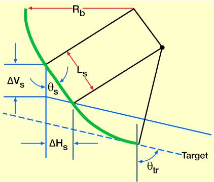
The straight section required to hit a sloping target (Figure 6) is

Sloping target, Build Curve Design, Horizontal Wells, Directional and Horizontal Drilling, Directional Drilling
FIGURE 6

L_{s} = \dfrac{\Delta H_{s}}{\sin \theta_{s}} (4)

\Delta H_{s}= \dfrac{\Delta V_{s}}{\cos \theta _{s}-\cos \theta _{tr}} (5)

where


Ls = length of straight section

ΔHs = horizontal displacement of straight section.

ΔVs= height to target slope.

θsθtr = straight section and target angles, respectively.

s = straight

tr = target

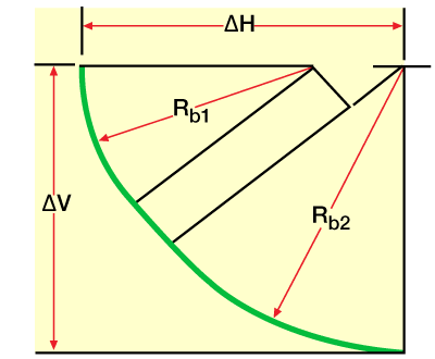
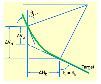
The build rate angle required to hit a sloping target (Figure 7) is

BR = \dfrac{57.3}{V_{tr}}\cdot \left ( \sin \theta _{i} - \sin \theta _{i -1} +\dfrac{\cos \theta _{i}\cdot \cos \theta _{i-1}}{\tan \theta _{tr}}\right ) (6)

where

BR = build rate

Vtr = vertical height from target

The build rate angle, Build Curve Design, Horizontal Wells, Directional and Horizontal Drilling, Directional Drilling
FIGURE 7

\Delta H = \dfrac{57.3}{BR}\cdot \left ( \cos \theta _{i-1}-\cos \theta _{i} \right ) (7)

\Delta V_{tr} = \dfrac{57.3}{BR}\cdot \left ( \sin \theta _{i}-\sin \theta _{i-1}+\dfrac{\cos \theta _{i}\cdot \cos \theta_{i-1} }{\tan \theta_{tr}} \right ) (8)

\Delta V = \dfrac{57.3}{BR}\cdot \left ( \sin \theta _{i}-\sin \theta _{i-1} \right ) (9)

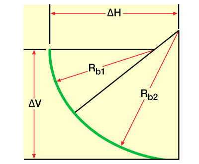
The tool face angle required for the second build is

\phi _{tf}= \cos^{-1} \dfrac{BR_{1}}{BR_{2}} (10)

The dog-leg severity is

DL = \left ( \theta _{i} -\theta _{i-1}\right )\cdot \left ( \dfrac{BR_{1}}{BR_{2}} \right ) (11)

The azimuth change is

\alpha = \left ( 57.3\cdot \tan \phi _{tf} \right )\cdot \ln \left [ \dfrac{\tan\left ( \dfrac{\phi _{1}}{2} \right ) }{\tan \left ( \dfrac{\phi_{i-1}}{2}\right )} \right ] (12)

where

ϕtf = tool face angle, degrees

DL = dog-leg severity, degrees

BR1= first build rate angle

BR2 = second build rate angle

The required final curvature build rate, BRr, to hit a target is given by

BR_{r} = \dfrac{57.3\cdot \left (\sin \theta_{tr} - \sin \theta _{i} \right )}{TVD_{tr}-TVD_{i}} (13)

where

θtr = target inclination angle

θi = present inclination angle

TVDtr = target true vertical depth

TVDi = target present true vertical depth


Previous page 1 2 3 4 5 6 7 8 9 10 11 12 13Next page

Related Articles

Leave a Reply

Your email address will not be published. Required fields are marked *

ad
Back to top button