Calibration of Gamma Ray Detectors and Well Logs
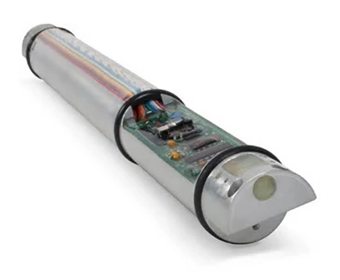
One challenge of gamma ray logging is choosing a standard calibration system. This is because the various LWD and wireline logging service companies use a variety of sensors (Figure 1) encased in different steel housings of various sizes and shapes. These logging tools will therefore not have the same efficiency, and thus will not provide the same count rate, even in the same borehole over the same interval. To address this issue, a calibration process was devised under the auspices of the American Petroleum Institute (API) to provide a degree of standardization for the calibration of gamma ray logging tools.
The API installed a test pit at the University of Houston in Texas that contains an artificial shale (Figure 2).

A cylinder 24 ft long and 4 ft in diameter contains a central 8-ft section consisting of cement mixed with 13-ppm uranium, 24-ppm thorium, and 4% potassium. Above and below the treated cement section are 8-ft sections of neat Portland cement cased with 5-1/2 inch J55 casing. The API standard defines the difference in radioactivity between the neat cement and the radioactively doped cement as 200 API units. Any logging service company may place its tool in this pit to calibrate it. The API test pit provides a degree of standardization but, despite the best efforts of tool designers, it cannot be expected that tools of different designs from different providers will read exactly the same under all conditions.
Field calibration of gamma ray logging tools is performed using a portable jig that contains a radioactive “pill.” Placed over the center of the gamma ray detector, the jig produces an increase over the background count rate equivalent to a known number of API units, depending on the tool type, size, and the counter it encloses.
Another challenge is the different logging speeds used to record gamma ray logs, especially between LWD and wireline logging modes, which affects the gamma ray statistics. Furthermore, some gamma ray logs are run centralized within the borehole, but others are run on wireline eccentralized, which affects the gamma ray count due to the different distance of the logging tool from the formation. Software can correct for the borehole effects (mud weight and composition, borehole size, and tool position in the borehole), so that the final tool response to a given formation is largely independent of the borehole environment.
Time Constants
Radioactive emissions are random phenomena that are subject to statistical variations. Because they vary in time, they produce statistical fluctuations on the gamma ray log. For example, if a radioactive source emits an average of 360,000 gamma rays per hour over a period of hours, then we can conclude that the source will emit 100 gamma rays per second, as an average. However, if the count is measured for 1 second, the actual count might be more or less than 100, thus forcing a choice. A relatively quick gamma ray count provides a poor estimate of the real count rate, while a long count yields a more accurate estimate of the count rate at the expense of greater rig time.
The logger must therefore choose among various time constants, according to the radioactivity level measured. The lower the count rate, the longer the time constant required for adequate averaging of variations. In the past, a simple resistor-capacitor (R-C) circuit was used, but now the averaging is carried out digitally after an analog to digital (A-D) conversion. The time-averaging constant (TC) helps to smooth the gamma-log. The faster the tool moves through the hole, the fewer gamma rays will be counted per depth unit, so a longer time-averaging period must be used to smooth out the statistical fluctuations.
On a typical logging job, gamma rays might be counted for a short period of time (such as one second); however, we must remember that during this 1-second time frame, the gamma ray detector will have moved past the formation whose activity is being measured. Thus, the logging speed and the time interval used to average count rates are interrelated. Table 1 provides the generally recognized guidelines.
Logging Speed | Time Constant |
|---|---|
| 3600 ft./hr. | 1 sec |
| 1800 ft./hr. | 2 sec |
| 1200 ft./hr. | 3 sec |
| 900 ft./hr. | 4 sec |
A theoretical example is shown in Figure 3.
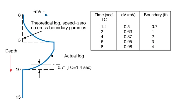
For a wireline logging speed of 1800 ft/hr and a TC of 2 sec, the time lag produces an apparent boundary displacement of about 1 foot. The averaging procedure causes a time lag on the log boundaries which increases with logging speed and TC, as demonstrated in the table embedded in Figure 5. The selection of the TC is a practical compromise of logging speed and log quality, as shown in Table 2. The standard for most logging jobs is 1800 ft/hr and a TC of 2 sec.
| Logging Speed ft./hr | 3600 | 1800 | 1800 | 900 |
|---|---|---|---|---|
| Time constant, (sec) | 5 | 5 | 2 | 4 |
| Statistical variations | low | low | fair | low |
| Travel during TC, ft. | 5 | 2.5 | 1 | 1 |
| Thin bed definition | poor | poor | good | good |
The parameters listed in the last column of this table can be used over short intervals for good bed definition. It is customary to maintain the product of the logging speed (ft/sec) times the TC (sec) at one foot.
The gamma ray tool’s investigation volume is a spherical shape around the detector. The depth of investigation is determined by:
- Rock density and mud density that attenuate the gamma-rays
- Natural GR energy
- Detector length (4 in., 8 in., and occasionally 12 in.)
A rough value for the vertical resolution is 2 feet, while the depth of investigation is about 1 foot.
When the efficiency of gamma ray detectors and their associated electronics improves by one or two orders of magnitude, the use of a time constant will become obsolete, except in the cases of extremely inactive formations with intrinsically low gamma ray count rates.
Perturbing Effects on Gamma Ray Logs
Gamma ray logs are subject to a number of perturbing effects as a consequence of the logging/borehole environment (Figure 4) including:
- Sonde position in the hole (centered/eccentered)
- Borehole size (Figure 5)
- Mud weight
- Casing size and weight
- Cement thickness in cased wellbores
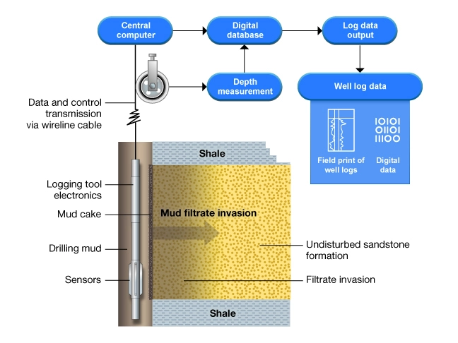
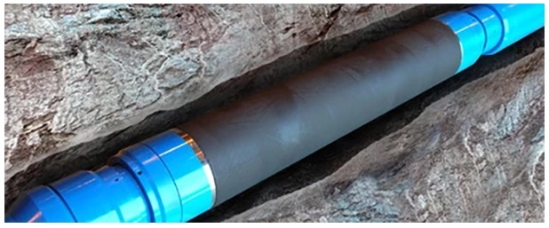
Because there are innumerable combinations of these effects, an arbitrary standard set of conditions for wireline logging operations has been traditionally defined as a 3-5/8 in. outside diameter tool, eccentered in an 8-in. borehole filled with 10-lb/gallon (ppg) mud. A series of charts, digitized into petrophysical analysis software, is published by each logging service company for making the appropriate corrections to their gamma ray log data. As logging tool technology evolves, such corrections are increasingly being made automatically in real time in the logging software. Log analysts should make the relevant corrections according to the vintage of the gamma ray acquisition and the logging tools used.
If a wireline gamma ray logging tool is run in combination with a density and neutron porosity device, it is run eccentrically because the density pad needs to be in contact with the borehole wall. If the wireline gamma ray log is run with a laterolog or an induction logging tool, it is run usually centered in the borehole, as there is no such requirement. LWD gamma rays are always run centered in the borehole on the bottom hole assembly, which eliminates one of the variables.
Gamma Ray Spectroscopy
Each radioactive decay produces a gamma ray that is unique in terms of energy level and abundance, and which is expressed in counts per time period. The simple method of counting how many gamma rays a formation produces can be carried a step further to count how many gamma rays from each energy group it produces. If the number of occurrences is plotted against the energy group, a spectrum can be produced that is characteristic of the formation logged.
Figure 6 shows such a spectrum where energies from 0 to approximately 3 meV have been split into 256 specific energy “bins” designated by channel numbers. The number of gamma rays in each bin is plotted on the Y-axis.
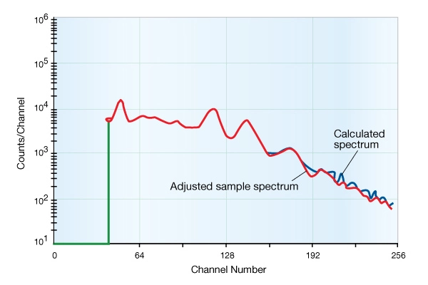
This spectrum can be thought of as a mixture of the three individual spectra belonging to uranium, thorium, and potassium. On-board computers in logging trucks are capable of quickly finding a “best fit” to produce continuous curves showing the concentration of U, Th, and K.
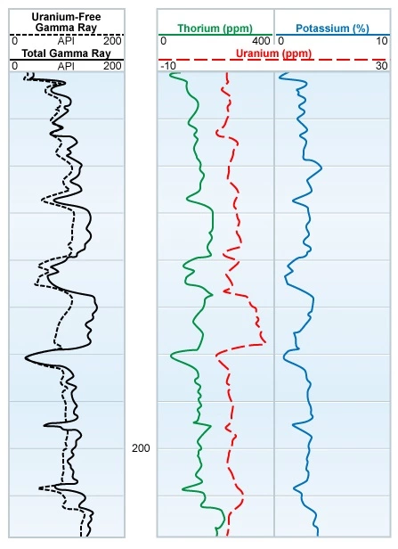
Figure 7 illustrates a gamma ray spectral log. Note that in Track I, both total gamma ray activity and a “uranium free” version of the total activity are displayed (units are API). In Tracks II and III the concentrations of U, Th, and K are displayed. Depending on the logging service company, the units may be in counts/sec, ppm, or percentage.
Gamma ray spectroscopy data acquired by a gamma ray spectral log can be used for lithology definition in both conventional and unconventional reservoirs.
 Petro Shine The Place for Oil and Gas Professionals.


