Related Articles


Multiphase Flow in Deviated Wells
Deviated wells with multiphase production present a unique problem to flow evaluation. In the schematic in Figure 1 and Figure 2,
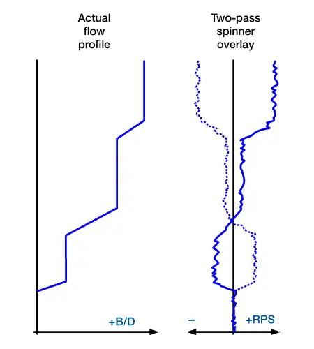
there are three sets of perforations, each producing oil with little or no water cut.
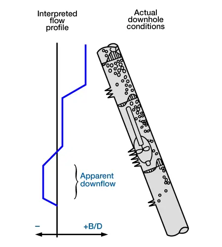
The actual bulk flow profile is shown on the left. When the oil enters the wellbore, it gravitates to the high side of the pipe and moves uphole along the pipe’s high side, carrying some water with it. If there is little or no water production, the water must fall back along the low side of the pipe, resulting in the flow profile shown in each interval. The flowmeter responds to the flow it sees, which is downflow in the lowest interval, upflow in the upper interval and somewhere in-between in the middle interval. This problem is minimized by centralizing the tool. Even with the tool centralized, this is a serious interpretation problem at lower flow rates and at deviation angles greater than 15º. If a small-diameter spinner is run noncentralized, interpretation problems occur at deviations of about 2º. The detection of a downflow in the lower parts of a deviated well should always be questioned.
This problem may be alleviated by using diverter-type flowmeters, which are available from major service companies. The Schlumberger inflatable diverter tool (Figure 3) is a typical example.
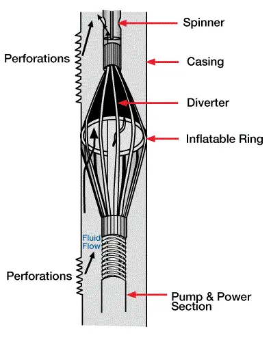
This tool utilizes a fabric diverting element and an inflatable tauroidal ring to divert the flow through the funnel-shaped test section. Other versions use metal petals attached to the centralizer arms to make a funnel element. These tools are much more effective than conventional flowmeters in deviated wells, but are limited to flow rates may impose limitations on their use, depending on the tool size and the service company.
The response of diverter flowmeters is precalibrated, and each tool and spinner combination has a unique calibration curve. Figure 4 shows the response of a typical diverting tool.
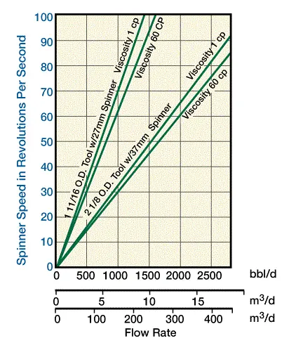
Responses of individual tools must be obtained from the service companies.
For multiphase flow, some tools contain a fluid-identification device, upstream from the spinner element. In a case where all of the fluid passing through the tool also passes through the fluid-identification device inside of it, the flow is very turbulent, and the holdup and cut are nearly equal. Either a nuclear densimeter or a capacitance device may be accurate under these conditions. Another alternative used by some service companies is to locate the fluid-identification devices directly above the exit ports of the diverter-type flowmeter. In flow loops, the holdup measured directly above the exit ports of a diverter tool closely matches the actual cut of fluids passing through the tool.
