Related Articles


Introduction to Drilling Hydraulics in Deviated Wells
Whether a well is directional or non-directional, the drilling mud and circulating system are keys to its successful drilling and completion. The topic Drilling Fluids and the Circulating System presents a detailed discussion of drilling fluids and circulating system components, while the topic Drilling Problems and Drilling Optimization discusses drilling hydraulics from the standpoint of drilling problems and optimization.
One of a drilling fluid’s primary functions is to remove drilled cuttings and transport them to the surface-in other words, to clean the hole. The term carrying capacity refers to a fluid’s ability to transport cuttings up the wellbore annulus to the surface.
If the mud’s hole cleaning abilities are inadequate, cuttings accumulate below the bit and in the annulus. This can lead to costly drilling problems.
- Cuttings accumulation below the bit results in inefficient drilling, premature bit wear, and reduced penetration rates.
- A high concentration of drilled solids in the annulus increases the effective mud weight, which reduces penetration rates. If the mud weight becomes too high, then lost circulation or even formation fracturing may occur, which in turn increases the possibility of well control problems (Adams, 1993).
- High cuttings concentrations in the annulus and around the bit tend to increase torque and drag. In severe cases, pipe may become stuck.
To prevent such problems from occurring, it is important to have a solid understanding of how the drilling fluid works to remove and transport cuttings.
Borehole Stability
Borehole stability analysis plays a crucial part in directional and horizontal well design and is critical to controlling drilling costs. The objective of a borehole stability analysis is to derive a safe window of mud weight such as that shown in Figure 1: A safe mud weight window is derived from borehole stability analysis.
The information required for a borehole stability analysis includes the following:
- Formation in-situ stresses.
- Borehole orientation with respect to the principal stress directions in the formation.
- Rock failure criteria.
The formation in-situ stress in the vertical direction can be estimated from a density log. The minimum horizontal stress can be derived from mini-frac test conducted in a pilot hole. The direction of the minimum horizontal stress can be determined from the orientated coring of the pilot hole. The maximum horizontal stress can be estimated based on the minimum horizontal stress, yield strength of rock, pressuring pressure, and pore pressure. Mohr-Coulomb failure criterion is usually employed for failure analysis.
Fluid Velocity and Flow Regimes
For a drilling mud to lift cuttings to the surface, its average annular velocity ( ) must be greater than the average slip velocity (
 ) with which the cuttings fall downward. The difference between and
  is the average cuttings transport, or rise velocity:
 (1)
(1)
 (2)
(2)
where Rt is the cuttings transport ratio. Recommended Rt values for vertical wells range from 0.5 to 0.55.
In a vertical well, slip velocity has only one axial component:
 (3)
(3)
On the other hand, when the annulus is inclined at an angle θ from vertical, slip velocity has two components:
 (4)
(4)
 (5)
(5)
where  and
and  are, respectively, the average slip velocity’s axial and radial components (Figure 1, Particle settling velocity in an inclined annulus).
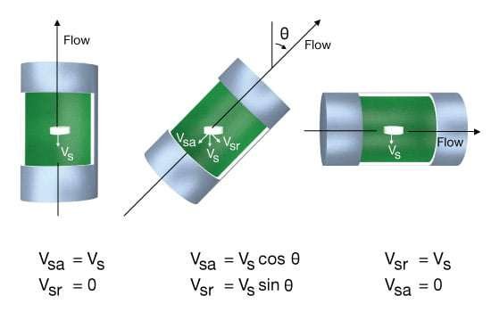
When the inclination angle increases, the slip velocity’s axial component decreases, becoming zero in a horizontal annulus. At the same time, the radial component reaches a maximum when the annulus is horizontal. Thus, factors that tend to improve cuttings transport by reducing particle slip velocity become less effective with increasing inclination angle.
In vertical drilling, the annular fluid velocity has to be sufficient to prevent cuttings from settling, and to transport these cuttings to the surface in reasonable time. In an inclined annulus, where the axial component of particle slip velocity plays a less important role, one might conclude that a proportionately lower annular velocity should be adequate to prevent particle settling. Such a conclusion, however, would be inaccurate. In reality, the increasing radial component of slip velocity in an inclined annulus tends to push cuttings toward the lower wall of the annulus, causing a cuttings bed to form. The annular velocity, therefore, has to be sufficient to prevent or limit bed formation. In general, annular velocities in directional wells have to be much higher than for vertical wells.
When considering cuttings transport phenomena, we must at the same time consider the fluid flow regime and vertical slippage. A fluid in turbulent flow always induces a turbulent regime of particle slippage, independent of the cuttings’ shapes and dimensions. In this case, the only factor that determines the particle slip velocity is the momentum of the fluid; fluid viscosity has little or no influence. If the mud is in laminar flow, then depending on the cuttings shape and size, we may expect either a turbulent or laminar regime of slippage. The laminar slippage regime will always provide a lower value of particle slip velocity, indicating that laminar flow will usually provide better transport than turbulent flow. In an inclined annulus, however, the significance of the axial slip velocity component decreases, tending to nullify the advantages of laminar flow.
Velocity Distribution Profile in Laminar Flow
The power law index n in the power law fluid model has a bearing on the mud’s velocity profile distribution in laminar flow, as shown in Figure 2 (Effect of power law index (n) on velocity profile).
As n decreases, the velocity profile becomes more flat. In vertical wells, this is advantageous to cuttings transport efficiency. However, in inclined wells with highly eccentric annuli, the decrease in n causes the hydraulic requirements for effective hole cleaning to increase. This is due to the increase in diversion of fluid flow from the narrow gap of the annulus to the wider gas as viscosity increases.
As shown in Figure 3 (Definition of annular eccentricity), the position of the inside pipe may vary.
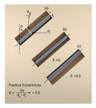
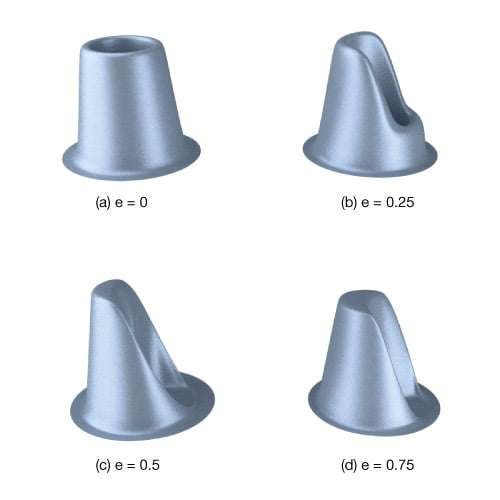
The displacement of the inside pipe toward the lower wall of the annulus (i.e., positive eccentricity) reduces the mud velocity in this area (Figure 4, Effect of eccentricity on annular velocity profile, and Figure 5, 3-D Velocity profile for yield power law fluid vs. eccentricity).
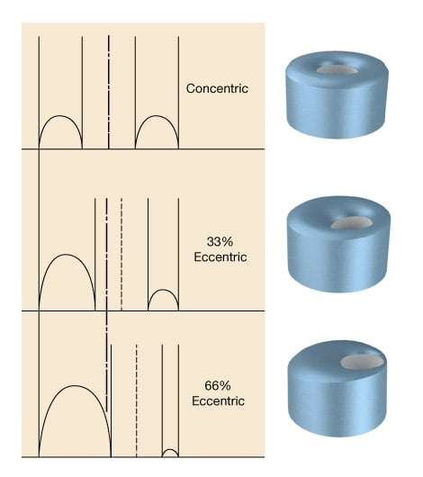
Cuttings transport problems thus become more acute for inclined wellbores with positive eccentricity.
Cuttings Transport
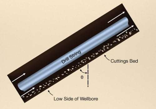
As hole inclination angle deviates beyond about 10° from vertical, the inclined, generally eccentric annulus begins to pose cuttings transport problems that are not encountered in vertical wells. For example, as hole angle approaches the 20°-to-30° range and fluid velocity is at some low value, a cuttings bed begins to form on the low side of the wellbore (Figure 1, Critical flow condition schematic).
To determine the hydraulics requirements for effective hole cleaning in inclined wells, we apply the concept of critical transport annular fluid velocity–this is the minimum annular fluid velocity for adequate hole cleaning. For wells with inclination angles of less than 35°, the critical transport fluid velocity corresponds to the annular velocity that results in no more than five percent by volume of annular cuttings concentration. On the other hand, for wells with inclination angles exceeding 40°, the critical transport fluid velocity corresponds to the minimum annular velocity that results in no stationary cuttings bed formation.
The following factors are thought to affect cuttings transport in directional drilling:
- Mud rheology: Based on full scale laboratory data, it appears that mud rheology has little or no effect on cuttings transport when the annular fluid velocity is greater than 120 ft/min, regardless of the inclination angle. At high inclination angles (θ>40∘), clear water drilling is slightly more effective in hole cleaning than a mud having yield point and plastic viscosity greater than 7 lb/100 ft2 and 7 cp (Figure 2,
Effect of mud rheology and hole angle on critical fluid velocity in 5″ hole, and Figure 3, Effect of mud rheology and hole angle on critical fluid velocity in 8″ hole).
- Eccentricity: For viscous muds, the drill string’s position in the wellbore becomes important with respect to hole cleaning. At high inclination angles, as eccentricity goes from positive (pipe on the low side of the wellbore) to negative (pipe on the high side of the wellbore), hydraulic requirements for adequate hole cleaning decrease. The opposite is true for clear water drilling. At low inclination angles, eccentricity has a minimal effect on hole cleaning.
- Mud weight: An increase in mud weight slightly enhances cuttings transport abilities, as long as there is not an accompanying viscosity increase. Mud weighteffects become more significant as inclination angle increases.
- Cuttings size: At high inclination angles, it is harder to transport smaller cuttings. At low inclination angles, it is easier to transport medium-sized cuttings than it is to move the smallest or largest-sized particles.
- Drilling rate: The drilling rate has an important effect on the quantitative aspect of cuttings transport. Increased drilling rates tend to increase the hydraulics requirements for effective cuttings removal. There is a linear relationship between drilling rate and required critical transport fluid velocity.
- Rotary speed: The effects of rotary speed on cuttings transport range from small to significant, depending on hole size and pipe diameter, hole angle, cuttings size, mud rheology and other well parameters. If drilling ceases, pipe rotation will always enhance the removal of the cuttings left in the annular space.
