Related Articles


Handling Guidelines
Mishandling, rough treatment and improper make-up can severely weaken oilfield tubulars. This is especially true for drill pipe, which is relatively thin and flexible compared to the rest of the drill string. Such weakening can lead to pipe or tool joint failures. To avoid such failures (and the fishing jobs that usually result), drilling personnel need to handle pipe with care.
Although drilling engineers are not normally involved in handling tubulars, it is important that they be familiar with proper procedures and observe that they are being followed. Such attention to detail will, in the long run, prevent well problems. The guidelines in this section, taken from Rowe and Wilson (1981), provide a summary of good handling practices.
Thread Protection
Steel thread protectors should always be used when picking up, laying down, moving or storing oilfield tubulars. General guidelines are as follows:
- Before picking up drill pipe from the racks, remove the thread protectors, thoroughly clean all connections and inspect the connections for damage. If solvent or other liquid is used for cleaning, the connections must be dried before applying thread compound. This thread compound should be of a high grade, and API-recommended for tool joint use.
- Re-install the thread protectors before moving the pipe onto the catwalk. Do not remove them again until the joint is picked up and the connection is ready to be made.
Pick-Up, Tripping and Lay-Down
Pick-up, tripping and lay-down procedures can have punishing effects on drill pipe and increase the chances of failure. Here are some guidelines for minimizing these effects:
- Before picking up, tripping or laying down pipe, inspect all handling equipment for proper operation and signs of wear, including the elevators, the rotary table, the master bushing, the slip bowl, slips, tongs and pull lines. Worn elevator bores, shoulders or latches could result in dropping the drill string, while a damaged or worn rotary table, master bushing, bowl or slips could lead to crushing of the drill pipe tube.
- Stagger breaks on each trip so that each connection can be checked and thread compound reapplied every second or third trip.
- Exercise care when running in the hole – run in slowly enough to avoid sudden impact on ridges or shoulders, to avoid tagging bottom and to prevent high surging or swabbing pressures.
- Do not use the slips as a brake to stop the downward drill pipe movement when tripping in the hole.
- Do not allow the slips to “ride” the pipe when tripping out of the hole.
- Use backup tongs when breaking connections; do not depend on the weight of the drill string to keep the pipe from turning in the slips.
- Set the slips with the tool joint as near as practical to the rotary table— this minimizes the possibility of bending the pipe during make-up or breakout.
- When picking up, laying down or standing back pipe, make sure that the catwalk, V-door and derrick floor are clear of foreign objects that could cause impact damage, and that the pipe is cleaned of any damaging or corrosive fluids.
Connections
Initial make-up is probably the most important factor affecting the life of tool joint connections. The following practices should be a part of make-up procedures:
- Pre-determine proper make-up torque, as specified for the particular connection, size, outside diameter and inside diameter.
- Use care when stabbing the pin connections into the box end, making sure that the pin does not strike the box shoulder or glance off the box threads.
- Make up connections slowly. High-speed kelly spinners or the spinning chain, when used on initial make-up, can cause galling of the threads. The driller should never jerk on the tong line to obtain proper make-up torque.
- Use a properly working, accurately calibrated torque gauge to measure the required line-pull as joints are made up to the required torque. This line pull is equal to the length of the tong arm (measured from the center of the tool joint, with the tongs in the set position at a 90° angle to the pull line) multiplied by the tong line pull.
Inspection
The IADC and the API have established detailed inspection guidelines for drill pipe and tool joints, which can be found in these standards:
- API RP 7G: Recommended Practice for Drill Stem Design and Operating Limits
- API RP 7G-2/ISO 10407-2: Recommended Practice for Drill Stem Element Inspection
Drill string failures result primarily from fatigue. The API defines a fatigue failure as one “which originates as a result of repeated or fluctuating stresses having maximum values less than the tensile strength of the material.” These stresses are products of the bending, torsion, vibration, tension and friction inherent in drilling operations, and are aggravated by corrosion, erosion, poor handling and other factors.
Fatigue failures are progressive; they generally begin as small cracks, which propagate as continued stress is applied. Unfortunately, fatigue is hard to detect in its early stages, and there are no accepted procedures for determining the amount of accumulated fatigue damage or the remaining life of pipe.
Accepted methods for inspecting the drill pipe tube involve:
- visual or magnetic particle inspection to locate cracks, pits and other surface marks;
- remaining wall thickness measurement, using either:
- pipe-wall micrometers;
- sonic pulse echo (resonance measurements);
- gamma ray devices, calibrated to within 2% accuracy;
- outside diameter measurement;
- cross-sectional area measurement, either by means of a direct-indicating instrument calibrated to within 2% accuracy, or by integrating wall thickness measurements taken at 1-inch intervals.
Required API procedures for inspecting tool joints involve:
- measuring outside diameter.
- checking shoulders for galls, nicks, washes, fins or other evidence of wear.
- randomly checking 10% of the joints for manufacture markings and installation dates to determine if the tool joint has been reworked.
Optional tool joint inspection procedures include:
- determining minimum acceptable shoulder width, as specified in API RP7G.
- measuring for box swell and/or pin stretch.
- examining thread profile for indications of overtorque, insufficient torque, lapped threads, galled threads and stretching;
- conducting a magnetic particle inspection if evidence of stretching or swelling is found.
Fatigue failure can occur rapidly under certain conditions. In areas that experience a high incidence of washouts or pipe failures, drilling personnel must be particularly selective about what they run in the hole, even if it means discarding joints for which the only signs of fatigue might be a few gouges in the slip area.
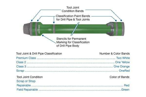
API 7G lists standards for classifying and identifying used drill pipe; Figure 1 shows where identification marks are applied.
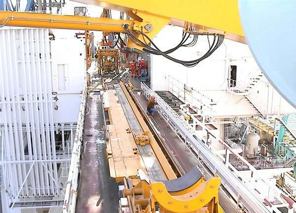
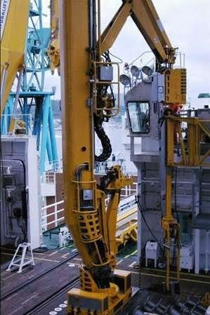
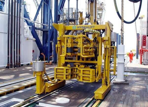
Automatic Pipe Handling
Automatic pipe racker systems provide a means of handling drill pipe by remote control. Operated from consoles on the rig floor (and, in some systems, from a derrick console) they use hydraulic, pneumatic or air power to latch and unlatch elevators, pull and set slips, make or break pipe connections, and lay down and pick up pipe. These systems are used primarily on floating drilling vessels, but are also available for use on platforms, jack-up rigs and land rigs.
Automatic pipe handling systems can provide dramatic savings on trip time and manpower, but their greatest benefit is increased safety. Safety is an especially important consideration on floating drilling vessels, where rough weather and heavy seas frequently render manual methods of pipe handling not only impractical, but dangerous.
Figure 2 (Horizontal handling system for conveying drill pipe and casing from the pipe racks to the rig floor), Figure 3 (Vertical handling system used to raise the pipe from horizontal, place it in vertical setbacks and finger boards for storage, and convey it to the center of the rig floor to be made up into the drill string) and Figure 4 (Iron roughneck used to make up the threaded pipe joints and torque them to precise specifications), taken aboard Japan’s deep sea scientific drilling vessel D/V Chikyu, illustrate the main components of an automatic pipe handling system.