Related Articles


Directional Drilling Sections
Now that we have reviewed the mechanical aspects of directional drilling, we can now describe the basic process of guiding the wellbore to the target. With the exception of the vertical portion of the well, there are three key segments of the wellbore that will most affect the geosteering project (Figure 1):
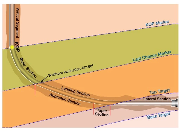
The Build Section is that portion of the directional wellbore curve that generally extends from the Kick-Off Point (KOP) to the Last Chance Marker, where the majority of the angle is built.
The Landing Section is that portion of the wellbore beyond the build section where the steering process is closely monitored and fine-tuned in order to hit the target. This section is further subdivided into two segments:
- The upper portion of the Landing Section is called the approach section, where major corrections to the trajectory can be made to setup the drill string to hit the target.
- The taper section forms a smooth transition at the end of the landing as the drillstring enters the target zone.
The Lateral Section is the section of the wellbore that extends horizontally from the end of the landing taper, out to the end of the wellbore.
The mechanics of geonavigation are basically the same for each section, but the Geosteering Team will find their priorities changing in from one section to the next.
The Build Section
The build section extends from the Kick Off Point (KOP) to the Last Chance Marker, or to a point where inclination reaches ±45 to 60 degrees (Figure 1).
The KOP may be defined strictly by depth, but should ideally be tied to a stratigraphic marker that will be expected at a preplanned distance above the reservoir target. Once the stratigraphic marker for the KOP is cut, the Geosteering Team may need to adjust the entire wellbore plan up or down – depending on how high or how low the marker was intercepted by the wellbore.
In cases where the target is below an unconformity, or in areas where there are no markers for correlation above the target, the well plan should place the KOP high enough in the section to provide sufficient room for building angle. It is better to place the KOP too high rather than too low.
It will be stressed again and again that the target for landing the well should be a line, rather than a point in space. This will give the Directional Driller more flexibility than a point specified strictly at a certain distance, direction, and depth from the surface location. The target line through the build and landing sections may actually become a moving target to accommodate the unforeseen presence of small faults or changes in formation dip rates. This reinforces the assertion that, through the build section, it is important to know where the well lies with respect to the stratigraphic framework of the prospect.
The formation dip between the surface location and the landing zone will exert a great influence as to where the target is actually intersected. It is important to keep track of the stratigraphic position of the wellbore throughout the build section by creating a True Vertical Depth (TVD) log or True Stratigraphic Position (TSP) log, and correlating it to the log from the pilot hole (if there is one) or to nearby offset wells. The Geosteering Team will use the TVD log to determine whether the well is drilling in an updip or downdip direction (Figure 2: Well log distortion with dip).
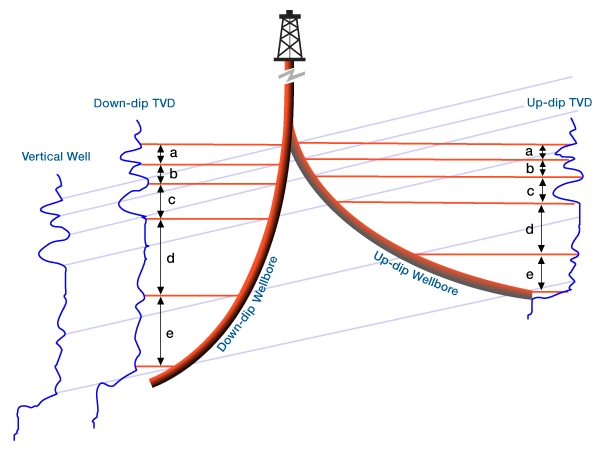
- If the TVD log from the horizontal LWD is thinner in the build section than the vertical offset, then the well is drilling updip.
- If the TVD log from the horizontal LWD is thicker, then the well is drilling downdip.
- If the TVD log is about the same thickness as the offset vertical log then the dip is relatively flat.
This TVD effect is more noticeable with increasing inclination and higher formation dip rates, but can also be noticed with dips as low as 2 degrees.
The Geosteering Team can then order minor adjustments to Build Up Rate (BUR), based upon their stratigraphic correlation.
One reason that it is better for a KOP to be too high rather than too low is because every BHA has a maximum BUR that it can attain. However, a lower BUR can be achieved either by wobbling the toolface, (turning the toolface a little left, then a little right) or by rotating the drillstring (most build assemblies cannot rotate, and extreme care should be taken with those that can). If the formation comes in higher than expected (usually due to an unexpected change in dip rate or a fault), then a trip may be required to adjust the BHA for a higher BUR before the build section is complete.
Last Chance Marker
The Last Chance marker is a stratigraphic marker that is used as the basis for making final adjustments prior to landing the well into the target zone (Figure 1: Last chance marker). This marker should be penetrated with a drillstring inclination of 45 -60 degrees. The Last Chance Marker is so named for a reason: when the Last Chance Marker is reached, it is the last opportunity for the Geosteering Team to decide whether to stay the course or to adjust the build rate.
- If the well is on target line and the BUR is within tolerance, then simply continue drilling with the same BHA.
- If the BUR is too high, and the well is above the projected line, then trip for a less aggressive BHA to land in target, or rotate the drill string if the BHA allows.
- If the BUR is too low and the well is below the projected line, then trip for a more aggressive BHA.
Effects of Dip
The last time it will be possible to make any major corrections to the BUR will be while the wellbore is at an angle of 45 to 60 degrees (depending on the formation dip and whether the well is drilled in an updip or downdip direction). There is less leeway on the target landing for an updip well than for a downdip well.
When a well is drilled in an updip direction, not only is the well building angle, but the formation is coming up toward the well. This leaves less room between the KOP and the target at the end of the curve.
If the well is drilled in a downdip direction, the formation falls away from the wellbore so that TVD distance increases between the KOP and the formation as the curve is built. It is nonetheless important to be positioned for the landing by the time that the wellbore inclination reaches 60 degrees. Once the Last Chance Marker is cut, or the wellbore reaches an inclination of 60 degrees (whichever comes first), the type of landing should be determined.
The Landing Section
The landing section is critical to the success of the horizontal well. The manner in which a well is landed depends on these important factors:
- the position of the bit at the end of the build,
- the BUR required to hit the target, and
- the presence (or lack of) good stratigraphic markers above the target
Drilling the Landing Section
The landing section is completed in at least two steps, as seen in Figure 1.
The Approach Sectionis the portion of the Landing Section that extends from the Last Chance Marker to a point where inclination is within 5 -8 degrees of formation dip. For instance, if the formation dips at 5 degrees and the well is drilling in an up-dip direction, then the approach section should end at about 88 -90 degrees. (Conversely, if the well was drilling downdip in the same area, the approach section would end with an inclination of 77 – 80 degrees.)
The Taper Section is the final stage of landing, and is generally performed with the maintenance assembly that will drill the Lateral Section.
There are a number of ways to approach the target (Figure 3):

Option One -Ideal Case: In the ideal case, the target will come in with the expected dip rates and planned BUR, so the landing can be continued with the current BHA until the taper section is reached. In this case, the build section is continued to within 5 to 8 degrees of the apparent formation dip. Then the BHA must be tripped to change from a build to a maintenance assembly. The curve will then be tapered into the target, and the drilling transitions to the lateral section.
Option Two -BUR Too High: If the BUR is too high at the Last Chance Marker, then there are two options.
- The first is to trip for a build BHA that will lower the BUR, then drill to the target, and trip again for the maintenance assembly.
- An alternate method is to continue with the current BHA until sufficient angle has been built to allow the maintenance assembly to complete the build, and then taper into the target. This will require only one trip versus two, but the GeoSteering Team must recognize that the landing will take place a little further out in the target zone. Ultimately, the GeoSteering Team must strike a balance between the cost of a trip and the loss of a little exposure to the reservoir.
For short laterals, the first method may be more appropriate. For long lateral sections, however, a little lost exposure at the end of the curve can be regained in the lateral section.
Option Three -BUR Too Low: When the build angle is too low for the current BHA to reach the target, then a trip will be required to pick up another BHA capable of attaining a higher BUR. This will require another trip for the taper and lateral sections, once the approach is completed.
Option Four -Tangent Approach: In areas where the target depth is uncertain because of a dearth of stratigraphic markers above the target, then a tangent approach should be planned. With a tangent approach, it is best to build angle to a point where a rotatable BHA can be used to drill the tangent section, then taper the landing. The tangent section is often drilled at an angle of 75 -80 degrees. This angle will depend greatly upon the level of uncertainty with regard to:
- the intersection with the target reservoir,
- the thickness of the target, and
- the apparent formation dip of the target.
Once the target formation is cut, the angle will be built to match apparent formation dip.
Casing Points
When setting casing at the top of the target, it is probably best to set casing before the taper is made, if the thickness of the target allows it. There have been a number of cases where angle was built to within one or two degrees of the predicted formation dip, only to have the bit unexpectedly penetrated the top of the zone upon drilling out of casing. This happens when the formation dip is steeper or flatter than the GeoSteering Team expected.
The Lateral Section
The Lateral Section is the most important segment of the horizontal well because it provides maximum exposure to the reservoir. (Again, seen in Figure 1.)
Any course change within the Lateral Section will affect the reservoir for better or for worse. The Lateral Section is drilled using a maintenance BHA. The maintenance BHA will have a mud motor configuration that allows the drillstring to be rotated. The inclination and azimuth of the Lateral Section is maintained through a combination of sliding and rotating of the drillstring.
The goal of many company Drilling Representatives or Wellsite Engineers is to slide as little as possible, because the bit cuts hole much slower in sliding mode. On the other hand, the Geosteering Team must ensure that the wellbore stays in the target zone. These two goals may often be at odds, so it is important that everyone be attuned to the goal of attaining maximum exposure to the reservoir.
The method of geosteering in the Lateral Section and the selection of a target line depends upon:
- the style of wellbore planned
- the thickness of the target
- the complexity of the geology
For instance, if a traverse or sinusoidal wellbore is supposed to be drilled through the target at a specified rate, then geosteering is used to ensure that the well does not pass through the section sooner (or later) than expected because of unanticipated changes in apparent formation dip rates. Small corrections should be made as the well is drilled to meet the reservoir penetration goals. For an in-zone well, the object is to stay as close to the apparent formation dip rate as possible. The closer that the drillstring is to dip, the longer it will stay in zone without correction.
Thin targets will require more target changes and closer supervision, while thicker targets give the driller more leeway (which means fewer slides are needed).
More steering decisions and closer supervision will be required in wells that are drilled in areas of complex geology.
Specifying Geosteering Target Lines
To get the most from the Directional Driller, the Geosteering Team should convey targets as lines, rather than points.
Directional Drillers can often be grouped into two camps with respect to target lines.
- One camp prefers to slide only when the well is about to drill beyond the given target tolerances. At that point, they will make a large correction with a long slide to be certain the well stays in target.
- The other camp prefers to make a series of small corrections to ensure that the well stays on target. This group feels that 3 -5 foot corrective slides provide the best course of action.
One point to remember is that the severity and position of doglegs are what cause torque and drag problems -not the number of slides.
In a long Lateral Section, the second camp will more likely reach projected length. This is one of the reasons that target lines work when points do not. A Directional Driller is more likely to stay closer to a line. Long slides of 20 feet or more should be reserved for the build or landing sections, and should be used sparingly within the Lateral Section. The only time large corrections should be made are after a fault is cut or to counter strong dip changes.
Occasionally, mechanical problems such as a formation change or torque and drag may prevent course corrections until a trip is made to clean the hole or change the BHA. After such a trip, a large correction may be needed to get back into target.
Guidelines for the Lateral Section
The Geosteering Team should develop contingency plans in advance of any major problems that may be encountered in the Lateral Section. The Lateral Section is more of a decision management exercise than either the Build or Landing Section, simply because it is more difficult to interpret the wellbore’s position within the targeted zone. GeoSteering Team guidelines for the Lateral Section include:
- Make decisions ahead of time: Contingency plans should be formulated before the well spuds in order to prescribe the general outline of response to a wide range of drilling scenarios. All that remains is to examine the data and act upon the decision. Often, in the excitement of the moment, there is a tendency to make decisions that do not adhere to the contingency plan, and hence fail to advance the objectives set forth in the plan. However, if a course of action can be planned under calmer conditions, before the event occurs, then adhering to the response plan will be easier.
- Make bailout or sidetrack contingencies, and then abide by them. When a fault is cut, or when a pinch-out is encountered, determine the throw and position of the well in-section after the fault, or confirm the pinch-out. If the throw is too great to recover, or if the formation has pinched-out, then follow the contingency plan.
- Make a target change ONLY WHEN THE GEOLOGY CHANGES. There simply is no other reason to make a target change. Target lines should only move when the wellbore begins to approach the target boundaries as a result of unforeseen changes in the formation.
- Make the least number of target changes possible to stay within the target. Every target change will affect the course of drilling in the remainder of the well. Doglegs increase torque and drag in the lateral section. Each dogleg adds to the problem, so the length of the lateral section is generally limited by the number of target changes.
- Thin targets with complex geology will require more target changes than thicker targets in simple geology. Thin targets, complex geology, and fast drilling can create nightmares for the Geosteering Team. These are the hardest type of targets to geosteer, and require constant supervision and intensive interpretation. Target changes for these types of reservoirs will be more frequent.
- Make steering decisions only when ALL of the critical data has been examined. Instant decisions that do not include all pertinent data are only guesses, and often cause more harm than good. The only mistake that the geosteering team should regret is the one made without first examining the data. A decision made through guessing or through panic can cause an unnecessary dogleg at minimum, or a sidetrack in the worst case.
- Mistakes in interpretation will invariably be made -so admit the mistake, recover, and continue. There are times when two perfectly reasonable interpretations fit the data. In these cases, it is best to look at more data to resolve the two interpretations (if possible). Many such cases actually resolve themselves in short order when more data is introduced. If the situation cannot be resolved with a reasonable amount of time and more data, then make the best choice and live with it. If it is discovered that the choice was not correct even after studying all of the data, then admit it and make plans to get back on target.