Related Articles


Directional Drilling Hardware: The Bottom Hole Assembly
The Bottom Hole Assembly (BHA) used in directional drilling consists of four special components that work together, making it possible to accurately steer a directional wellbore:
- Bit
- Bent sub
- Mud motor
- MWD tool
Each of these components is described below.
(Note that the mechanical aspects of directional drilling are described in much more detail in the IPIMS module on Directional and Horizontal Drilling, found in the Drilling Engineering Series, under the Petroleum Engineering Discipline.)
The Bit
Bit selection is key to the effective drilling of a horizontal wellbore. A balance must often be struck between the durability, rate of penetration (ROP), and steering stability of the bit. Bit trips in horizontal wellbores can be very expensive, so bit durability is a key factor in the overall cost of drilling. Ultimately, the ROP should be maximized to make as much hole in as little time as possible (including trips for bit changes). However, if ROP is maximized at the expense of reducing the capability to maintain the intended course, then any cost savings realized by fast ROP is negated because the well will not stay on target.
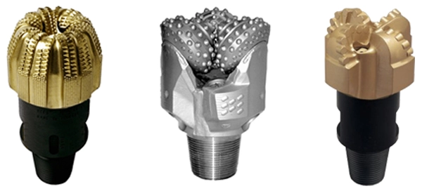
Each formation reacts differently to specific bit designs (Figure 1: Diamond, Roller Cone and PDC bits). Bit selection of cone bits, PDC bits or impregnated bits will depend on the section that must be drilled. Most bit manufacturers have a variety of bits in each class to suit the application. It is often best to defer to local experience in guiding the bit selection process.
The Bent Sub
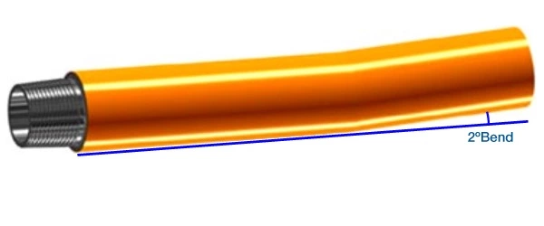
The bent sub is located above the bit and beneath the hydraulic turbine. This sub is bent at just a small angle (typically ranging from 0.2 degrees to a just couple of degrees), as shown in the following Figure 2. A number of subs have been designed so that the angle can be adjusted to meet different applications (Figure 3: Changing the angle of the). The bent sub plays an important role in providing the fulcrum necessary to change the direction of the wellbore.

The toolface of this sub is defined as the direction, relative to the high side of the hole, in which the convex face of the bend is oriented. Toolface orientation is specified as X-degrees left or right, with 0 degrees pointing the toolface straight up (Figure 4: Toolface set at 130° left).

To orient the toolface, the Directional Driller slowly rotates the drillpipe at the surface, pointing the toolface toward the direction where angle will be built. Once the toolface is set, the mud motor is engaged while keeping the drillpipe stationary at the surface. The bend points the bit in a direction that differs from the axis of the wellbore. The hole then cuts differentially in the direction of the toolface, causing the wellbore to deviate in that direction and to continue building angle.
Once the desired wellbore azimuth is attained, that azimuth may be maintained by rotating the entire drillstring (including the bent section). Now, instead of the bit drilling in a single direction off the wellbore axis, it will sweep around, with the result that its net direction will coincides with the existing wellbore.
Some tools allow steering while rotating, thus achieving higher rates of penetration.
The Mud Motor
The mud motor consists of a hydraulic turbine, which is driven by the force of the drilling fluid that is pumped down through the drillpipe (Figure 5: Mud motor). The mud motor turns the bit without the usual necessity of rotating the entire drill string.

The MWD / LWD Tool
The next component in the BHA is the Measurement While Drilling (MWD) tool. The MWD contains instruments to measure toolface orientation, along with borehole azimuth and inclination or other measurements.
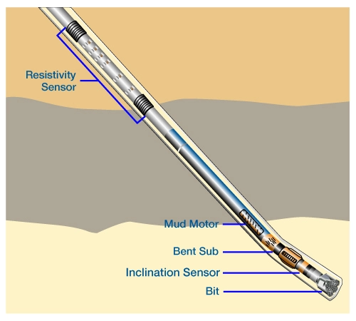
Often, a suite of Logging While Drilling (LWD) tools are included as part of the downhole measurement package. A typical LWD tool string might include such devices as the Gamma Ray, Resistivity, Density, Neutron, and Sonic logging tools (Figure 6: Typical MWD/LWD tool string).
MWD/LWD tools transmit their measurement data to the surface by way of mud pulse telemetry. A pulser or transmission module sits atop the tool string to transmit data uphole (Figure 7: Telemetry/Pulser module).

The data obtained by MWD/LWD tools can be stored downhole in the tool’s memory modules should the mud pulse unit fail.
Many aspects of MWD/LWD operation are similar, however,
- MWD usually refers to directional and pressure sensors.
- LWD usually refers to the formation evaluation sensors.
Downhole Data Transmission
The drilling or petrophysical parameters measured below the mud motor or at the bit can be digitally encoded and transmitted to the surface on a real-time basis. For instance, toolface direction can be measured and sent to the surface for real-time control of the bit orientation.
A telemetry system is used to relay data from sensors located near the bit to the MWD tool, positioned further up the hole (it can range up to 200 feet behind the bit). This telemetry path actually bypasses the intervening drilling tools (such as the mud motor) between the bit and the MWD tool. Typically, an MWD pulse system receives the signal from the near-bit telemetry link, then recodes it and sends the data to the surface in real time, using mud-pulse telemetry (other telemetry methods can also be used, as described below). Data recording, interpretation and tool control are monitored by the system computer at the surface. From the surface, control instructions can be sent back downhole by varying mud pump flow.
Data can be transmitted to the surface by a number of methods:
- Mud-Pressure Telemetry
- positive pressure pulse,
- negative pressure pulse, and
- continuous wave
- Electromagnetic Wave Telemetry
- Drill Pipe Telemetry
Each of these methods will be described below.
Positive Pressure Pulse
The most common method uses a positive pressure pulse system. With this type of system, a hydraulic poppet valve momentarily restricts the flow of the mud through the drillpipe, creating a positive standpipe pressure pulse. Data is transmitted to the surface as a series of pressure pulses. A transducer at the surface detects the pressure changes and a computer decodes the signal.
Negative Pressure Pulse
A negative mud pulse system uses a control valve in the sub to vent mud from the interior of the tool to the annulus, thus creating a drop in pressure at the standpipe. Data is recorded at the surface in a manner similar to that described above.
Continuous Wave
Continuous wave telemetry uses a downhole rotary valve with a slotted rotor and stator to restrict the mud flow through the MWD tool, thus generating a modulating positive pressure wave which travels to the surface and is detected by the transducer at the standpipe.
Electromagnetic Telemetry
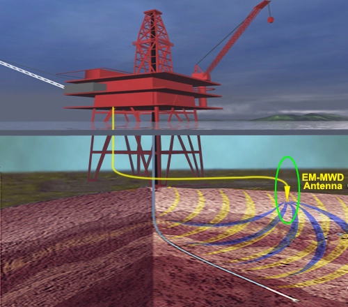
A different method has been devised for use in cases where a compressible drilling fluid is used (such as underbalanced drilling,) or in areas where severe lost circulation prevents transmission of a pressure pulse up the drillpipe. Developed as an alternative to mud-pulse telemetry, this system uses low-frequency electromagnetic waves to transmit data from the MWD tool to the surface. Instead of drilling fluid, the electromagnetic MWD tool (EM-MWD) relies on geological formations to conduct the data to a surface antenna, where it is relayed to an acquisition unit for decoding and processing. (Offshore, the antenna must be coupled to the sea-floor, as seen in Figure 8: Offshore installation, yellow waves show data transmitted from tool to surface, blue waves show instructions transmitted from surface to tool.)
The EM-MWD tool transmits toolface, inclination, and azimuth data for directional surveys. It is often fitted with a gamma ray tool to provide formation boundary definition for real-time correlation. An annulus pressure gauge can also be added to directly measure pressures during drilling and tripping operations.
The EM-MWD requires no modification to the rig’s drilling fluid circuit, and can operate continuously during all phases of drilling operations, including pipe connections and trips. Because EM-MWD systems do not depend on rig hydraulics to transmit their data, they are not plagued by problems common to mud telemetry systems such as bit-pressure drops, fluctuating flow rates, lost circulation materials, or mud losses to the formation. (However, the EM-MWD system has experienced difficulties in high resistivity formations, so to avoid problems with signal propagation and attenuation, it should be installed in high conductivity formations.)
This system provides two-way communication between the surface unit and the downhole tool. Data is transmitted from the tool to the surface, and instructions can be sent from the surface to the tool. The EM-MWD system is able to collect and transmit survey data while the surface mud pumps are running or idle, as long as the drillstring does not move.
Though used in conventional, horizontal, and directional drilling operations, this system is seeing increasing utilization in underbalanced drilling, as such wells become more popular in older, depleted fields. Because these wells frequently employ unconventional drilling fluids such as foam, mist, air, or aerated mud, the EM-MWD is often fitted with an annulus pressure gauge to monitor drilling operations.
Drill Pipe Telemetry
Drill pipe telemetry offers the capability of transmitting high-bandwidth data from any point along the drill string. This system requires specially manufactured drillpipe, incorporating a high-speed cable attached to the inner wall, and special couplers at the ends of each joint of pipe. (Figure 9: Cut-away view of IntelliPipe drill pipe telemetry system, developed by Grant Prideco and Novatek Engineering).
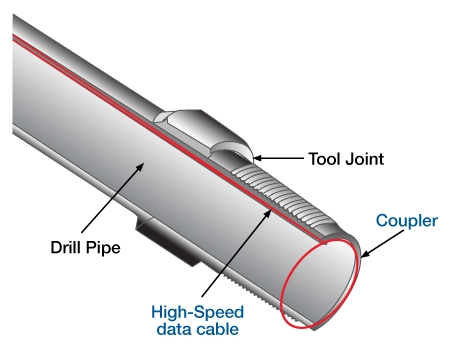
This special cable and coupler arrangement enables data to be transmitted up the hole at a rate of 1 million bits per second, which is several thousand times faster than mud-pulse telemetry systems. The drillpipe telemetry system is virtually transparent to standard rig operations, requires no special pipe-handling or make-up procedures, and works as long as there is pipe in the hole.
This high-speed, bi-directional communications link can be integrated with downhole temperature and pressure sensors; steering systems; MWD or LWD systems; remote and Web-based monitors and analytical tools; and acoustic systems. This system allows the Geosteering Team to receive high-speed data for up-to-the-minute analysis. It also enables the Directional Driller to relay steering commands downhole more quickly in order to drill more precisely toward oil-and gas-bearing sweet spots and away from less productive areas.