Related Articles


Core Processing Report
The best practice is to document the core processing steps and include these in the core analysis report, as in the example below:
Spectral Gamma Ray Log
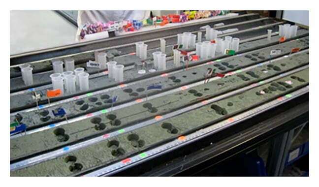
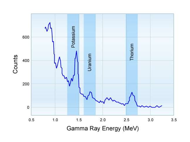
Each core was scanned to measure its natural gamma ray radiation using the Core Service Company’s gamma ray spectrometer (Figure 1). The cores were sampled by the spectrometer’s detector at a rate of one-half foot per minute. The total gamma ray radiation is reported in API units. Potassium, uranium and thorium levels (Figure 2) were recorded, as these are the three radioactive elements primarily responsible for a typical rock gamma ray spectrum and support studies of the depositional environment using cores (Rothwell, 2006). The Core Service Company’s gamma ray spectrometer reports the concentrations of uranium and thorium in parts per million and that of potassium as a percentage. During the gamma ray logging of the core, one observer verified that each barrel passing the detector was in its correct sequence and orientation, while two people loaded, and two people offloaded the barrels. As each barrel cleared the detector it was replaced in sequence on the layout benches. The preliminary digitized gamma trace was sent to the oil company operator once each core had been run.

Core Slabbing
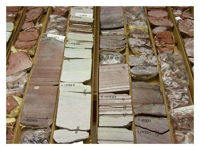
The chilled core segments were slabbed (Figure 3) parallel to the core axis with a one-third and two-thirds cut. Liquid nitrogen was used as the slab blade coolant. The one-third sections of core were mounted in slab boxes with styrofoam inserts. The upper surfaces were scraped to remove the cuttings and saw marks. The one-third slabbed sections were then returned to the chiller pending viewing by the oil company’s representatives. The two-thirds sections of core were returned to their original core boxes and returned to our on-site chiller pending instructions from the oil company.
Sample Preparation
One inch diameter plug samples (Figure 4) were drilled from each selected foot of the core (Figure 5). Liquid nitrogen vapor was used as the bit coolant. Each plug was encased in a thin-walled metal jacket and fitted with 120 mesh end-screens. The jackets were set to the plugs under hydrostatic loading conditions at a pressure equal to 400 psia confining pressure.