Related Articles


Surface Mixing and Pumping Equipment
Figure 1 illustrates the typical cement mixing and pumping equipment on a drilling rig location. Water is added to the cement via a displacement tank system that includes twin 10-barrel or 20-barrel tanks. If liquid additives are not premixed with the water, they are metered into the displacement tank.
The water/additive mixture is pumped from the tank system using a low pressure centrifugal pump via a mixing water manifold, to the cement mixer.
Typical Mixing and Pumping Equipment on Rig Site

1. Centrifugal water supply pump
2. Water distributor
3. Additive distributor
4. Displacement tank system
5. Mixing water pump (centrifugal-low pressure mixing; reciprocating-high pressure mixing)
6. Mixing water manifold
7. Cement mixer (conventional jet mixer shown)
8. Slurry tub
9. Centrifugal pressurizing pump
10. Reciprocating displacement (downhole) pumps
Cement Mixing Equipment
The cement mixer can be a conventional jet mixer (Figure 2), or a recirculating mixer. This element of the system combines the dry cement/dry additive mixture with the water/liquid additive mixture to create the slurry. In the case of a recirculating mixer, the slurry can be diverted back through the mixer to improve the homogeneity of the slurry. The dry material can be added one sack at a time or air-jetted from a surge tank.

The jet mixer is designed to induce a partial vacuum at the venturi throat at the bottom of the cone, drawing in the dry cement. A conventional jet mixer can produce up to approximately 2200  of slurry. Slurry density is adjusted by adjusting the rate of water and/or cement addition to the mixer. Turbulent flow mixes the slurry as it moves from the mixer through the “gooseneck” to the slurry tub. The jet mixer is simple, reliable, and rugged, and typically can handle about 50 sacks of cement per minute when they are being added by hand.
Pumps and Cementing Units
After it is mixed, the slurry is pumped from the slurry tub through a centrifugal pump to the high pressure triplex pump(s) that pump the slurry into the well. These heavy duty, positive displacement triplex pumps operate with hydraulic horsepower between 200 and 500 HP depending on the model of pump. These are the same types of triplex pumps that are used for hydraulic fracturing.
The pump rate is typically approximately 8 barrels per minute and the pressure is under 1,000 psi. High pump rates are 10 to 15 barrels per minute. The rate is usually limited by the burst pressure of the steel pipe through which the slurry is pumped from the cementing unit to the well.
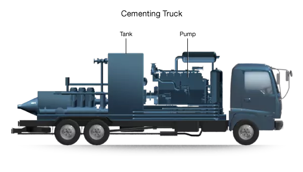
Cementing units can be skid-mounted for use on offshore platforms or shallow-water barges, or truck-mounted or semi-trailer mounted for use on land (Figure 3).
Traditionally, a cementing unit includes two of every vital element, so that a malfunction at a critical moment does not jeopardize the cementing job or possibly the well.

In operation, the pumper draws slurry from the mixer in a predetermined volume calculated from sacks and yield. Meanwhile, displacing fluid is drawn from storage to two open tanks on the pumper. The slurry is followed immediately by the displacing fluid, which is gauged by the alternate draining and filling of the two tanks. When nearing the end of displacement, slower rates are preferred, to decrease the possibility of plug or casing damage.
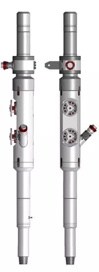
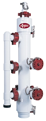
Cementing Head
Cement slurry is pumped from the cementing unit via flow lines to a cementing head located on the drilling rig floor (Figure 5). The cementing head connects the casing to the cementing unit flow line and the displacement fluid flow lines.

Internally, the cementing head holds the displacement plugs and setting balls that will be “dropped” into the casing as the cementing job progresses.
There are two types of cementing heads:
- A conventional head is used for conventional drilling rigs, and sits atop the casing head supported by the conductor pipe (Figure 6).
- In the case of a top drive system, the entire weight of the casing or casing liner is supported by the equipment as it hangs in the derrick. With a top drive system the casing can be rotated or reciprocated while pumping is underway. Top drive cementing heads (Figure 7) permit plugs and darts to be dropped via a wireless control system and valves to be operated via pneumatic controls.