Load Response: Airy Isostasy Compensation Model
Airy isostasy is a conceptual and quantitative model of how crustal loads deform the lithosphere. In an Airy model, we assume that all loads are compensated locally and that the lithosphere has no lateral strength. In this view, the lithosphere consists of columns extending from the surface to a depth of compensation (Figure 1, Isostatic compensation of column loads A through E.
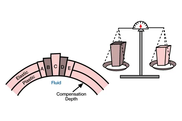
Loads are supported by bouyancy forces within the fluid atmosphere. Above a compensation depth within the fluid, each column load weighs an equal amount. The volumes of the columns differ because columns with less volume [less think and shaded darker] have higher average densities than columns with more volume [thicker and shaded lighter]. At depth of compression, pressure is constant, or isostatic). Each column is isolated mechanically from adjacent columns as if each has Teflon-coated sides so that shear stress cannot be transmitted across column boundaries (Figure 2, Flexural and local compensation occurs where layers within the lithosphere have sufficient lateral strength to support the load, as if the layers were connected by springs.
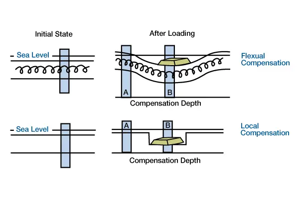
The load depresses the lithosphere beneath and adjacent to the load. In local compensation, layers within the lithosphere have no lateral strength [no springs] to support the load. The load depresses the lithosphere only at the position of the load.). Because we do not consider lateral lithospheric strength, the deflection we calculate using an Airy model will occur directly beneath the load. The Airy model also assumes that the load is compensated instantaneously. Each column moves up or down immediately as a load is emplaced or removed.
In an Airy model, we base our calculations of deflection on the concept of buoyancy, which assumes equal weight distribution above a compensation depth within a fluid asthenosphere. Figure 3, (Calculation of subsidence caused by a sediment load using Airy compensation model.
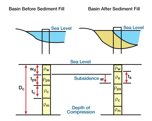
Column weights are calculated between sea level and a depth of compensation in the asthenosphere), shows a sample Airy calculation for a sediment load in a water-filled basin. Sea level remains constant for this calculation and there is no tectonic subsidence or compaction. The only deflection we consider is the deflection caused by compensation of the sediment load. The compensation depth, Dc, is an unspecified depth in the mantle-asthenosphere. Two surfaces constrain the solution: a depth of compensation in the asthenosphere and an imaginary surface within the earth’s atmosphere. Within fluids, pressure is equal along each of these surfaces. The Airy model requires that the total column mass between these surfaces be constant before and after the sediment load is deposited. (We assume that the weight of air is negligible for this calculation.) Because we assume that the columns extend infinitely into and out of the paper, the mass of each column above and below the compensation depth is its thickness multiplied by its density. Thus, the mass of a column above the depth of compensation before and after sediments are deposited is
![]() (1)
(1)
![]() (2)
(2)
Each of the terms and their units are defined in Table 1 . We can determine the deflection, w, by equating the right sides of Equations 1 and 2. Then, after collecting terms and solving for the deflection, we get
| ρw | Density of water (g/cm3) |
| ρps | Density of previous sediment (g/cm3) |
| ρc | Density of crust (g/cm3) |
| ρm | Density of mantle (g/cm3) |
| ρs | Density of new sediment (g/cm3) |
| ρr | Density replacement mass (g/cm3) |
| Wd | Initial water depth in (meters) |
| tps | Thickness of previous sediments (meters) |
| tc | Thickness of crust (meters) |
| Dc | Depth of compensation (meters) |
| ts | Thickness of new sediments (meters) |
| w | Calculated subsidence (meters) |
![]() (3)
(3)
Given typical values for these densities (ρw=1.0 gm/cm3, ρs=4 gm/cm3, ρm=3.4 gm/cm3), the maximum deflection due to a sediment load is 0.6 ts, or approximately half the thickness of the sediment.
Notice that the depth of compensation, Dc, and the weight of previous loads between the new load and Dc (e.g., the crust and previously deposited sediments) do not appear in the final expression. There are no density changes in these layers, and they do not influence deflection. The concept of summing masses above a compensation depth assumes that the ratio of incremental changes in loads and density distributions determines the magnitude of deflection.
Because the sum of the column masses not their vertical positions is important, we can rearrange the masses between the two constraining surfaces to illustrate how masses are replaced in Airy compensation (Figure 4, Method for calculating subsidence caused by isostatic compensation of a sediment mass.
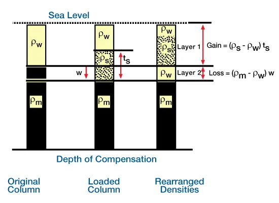
There is a net gain in mass in Layer 1 because the new sediment mass replaces water. There is a net loss in Layer 2 because water replaces mantle material. The net mass gain of Layer 1 must equal the net mass loss of Layer 2.). Because densities of the crust and previously deposited sediments do not influence our deflection calculations, we do not include them, and instead fill their space with mantle material.
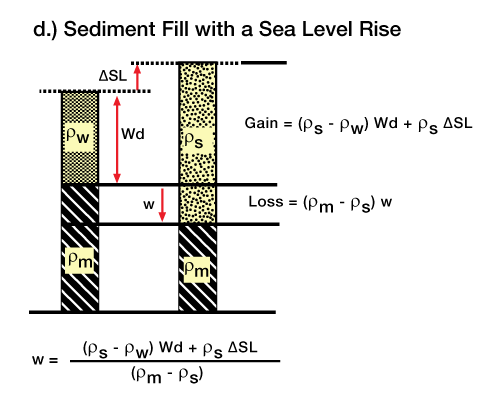
For this model, there are two layers of mass replacement. There is a net gain in mass in Layer 1 because the new sediment mass replaces water. The thickness of Layer 1 is equal to the previous water column. Because sediment was deposited below sea level, and because a lithospheric deflection also deflects the asthenosphere, we effectively replace the deflected mantle with sea water above the sediment interface. We move the column of water that fills the deflection below the sediment column to illustrate that it is replacing deflected mantle, causing a net loss of mass in Layer 2. Because we assume the total column masses are constant, the net gain in mass in Layer 1 must equal the net loss of mass in Layer 2. Equating the expressions for gain and loss and solving for deflection gives us Equation 3. Figure 5 (Subsidence caused by level rise without sediment input),
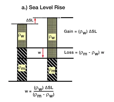
Figure 6 (Uplift caused by a sea level fall without sediment input),
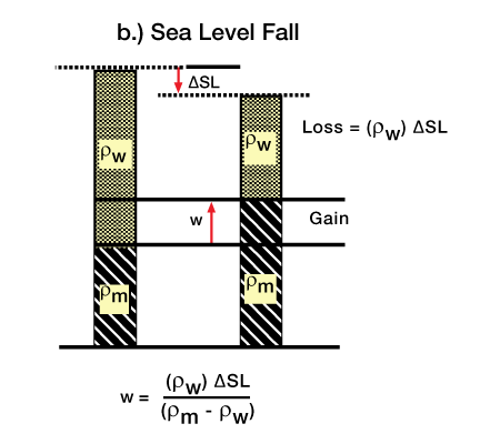
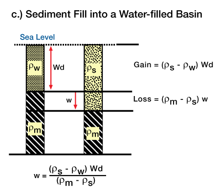
Figure 7 (Subsidence caused by sediment filling a water-filled basin),
and Figure 8 (Subsidence caused by a sea level rise and sediment fill), illustrate how we can use this method to calculate the Airy response for several common load situations. In general, the Airy deflection equation will be of the form:
![]() (4)
(4)
The incremental load in the numerator corresponds to the net gain in mass. The denominator corresponds to the net loss of mass as the displaced mantle is replaced with a mass of density ρr.
Using the Airy model to fill a water-filled topographic basin with sediment illustrates the need for tectonic forces in basin development. The Airy response, as derived in Figure 5, Figure 6, Figure 7, and Figure 8 give a deflection of:
![]() (5)
(5)
Using typical values for these densities, we get a maximum deflection value of approximately 1.4 times the initial water depth, Wd. The final thickness of strata filling the topographic basin will be the sum of the initial water depth, Wd, and the deflection, w. Therefore, the maximum thickness due to sediment filling of a previous topographic depression is approximately 4 times the depth of the original depression. Basins are commonly filled with sediments to thicknesses of 3 km or more and it is clear that sedimentary basins of typical thickness cannot be due solely to the filling of an initial topographic depression of 1.25 km (3 km≠4×1.25 km). And, most sediments filling this basin would indicate extremely deep water depths. So, we can conclude that loading by sediment a sort of perpetual motion machine is an insufficient mechanism for forming most basins and that tectonic forces are necessary.
 Petro Shine The Place for Oil and Gas Professionals.


