Related Articles


Wellbore deviation refers to the degree to which a wellbore deviates from the vertical or the planned trajectory. Deviation can occur naturally due to geological formations or intentionally by directional drilling techniques to reach a specific target zone or maximize reservoir exposure.
Wellbore deviation is typically measured in terms of the deviation angle and the azimuth angle. The deviation angle is the angle between the wellbore and the vertical plane, while the azimuth angle is the angle between the wellbore and a reference direction, usually north.
Causes of Wellbore Deviation
Because of its elasticity, its tendency to buckle under axial forces and its inability to withstand lateral forces, the drill string has long been recognized as a key to controlling wellbore deviation. The role of the drill bit has been less obvious, although it has long been known that forces at the bit can affect its path. These forces vary among different bit types even in the same formation, indicating that bit design and geometry relate to wellbore deviation. Still, most studies on wellbore deviation have focused on the drill string, accepting the idea that weight-on-bit is the principle contributor to deviation.
Although the exact causes of wellbore deviation are unknown, we can list the following as contributing factors:
- Formation type (i.e., lithology, anisotropy, dip)
- Bottomhole assembly size and configuration (i.e., stabilizer types, size, positioning; drill collars; reamers and other tools)
- Drilling parameters (i.e., weight on bit, hydraulics)
- Hole angle
- Annular clearance
- Bit type, design features
Wellbore deviation results from forces acting at the bit. We can separate a study of these forces into two parts:
- Bit/rock interaction – the study of bit behavior in various rocks under the action of applied bit loads
- Drill string mechanics – the analysis of drill string behavior under the action of imposed forces
Bit-Rock Interaction
We can break down the mechanical actions of drilling a rock into three categories: percussive action, drag-rotary action and combined percussive/drag-rotary action (Figure 1, Parameters affecting hole deviation that are due to rock/bit interaction):

Rolling cutter bits employ a combined percussive/drag-rotary action, while, fixed cutter bits fall into the drag-rotary action category.
Parameters that affect hole deviation based on bit/rock interaction relate to rock properties, bit characteristics and drilling variables. Table 1 , below, lists the most important of these.
| Rock properties | Bit characteristics | Drilling parameters |
|---|---|---|
| Cohesive strengt | Roller cone: | Depth of cut/ weight on bit |
| Angle of friction | Number of teeth or inserts per given row of a cone | Rotary speed |
| Angle of bedding planes | Half-wedge angle of bit tooth | |
| Degree and type of anisotropy | Bit diameter Amount of cone offset PDC: Number of cutters Cutter size and shape Bit diameter Rake angles Bit profile |
Drill String Mechanics
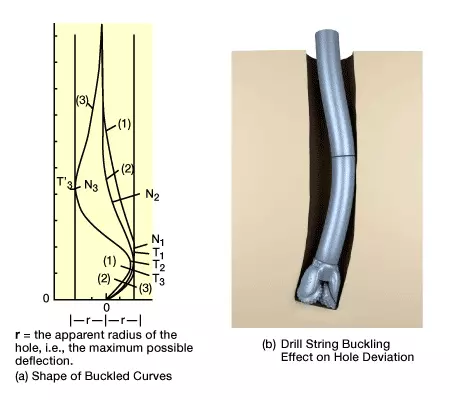
The deviating forces that the drill string imparts to the bit relate directly to the string’s configuration, the hole geometry, and the weight on the bit. Structurally speaking, a drill string is a flexible, elastic member, unable to resist lateral loads and subject to buckling under axial loads. The shape of this buckling depends on how much weight is applied at the bit (Figure 2, Shape of buckled curves (a) and drill sting bucking effect on hole deviation (b)). Once buckling occurs, the bit is no longer vertical, and hole deviation results.
The extent to which buckling occurs depends on the drill string’s rigidity and length. Techniques that have been used to minimize buckling include:
- reducing weight-on-bit to a value less than that of the critical weight which induces first-order buckling
- adding stabilizers to the drill string at points of maximum deflection in the predicted buckling mode
- using large-diameter drill collars
From the standpoint of reducing buckling, the ideal bottomhole assembly (BHA) would have a diameter equal to the hole diameter. Of course, this is a practical impossibility, so we instead use stabilizers (Figure 3), which have larger diameters than drill collars, to limit the BHA’s lateral movement.

Deviation Forces on an Unstabilized Bottomhole Assembly
Factors that are of practical importance in affecting drill string behavior include:
- drill collar stiffness and unit weight
- hole inclination
- clearance between the drill string and the hole
- weight-on-bit
- formation characteristics
Figure 4 (Idealized sketch of forces affecting hole deviation angle), which shows a bottomhole assembly in a straight, inclined hole (angle of inclination =α.) illustrates the forces acting on the bit to cause deviation.

In analyzing these forces, we assume that the bit is free to turn, but laterally restrained; that the drill collars lie on the low side of the hole and will remain stable there; and that the bit will drill in the direction in which it is pushed, which is not necessarily the direction in which it is aimed.
The force with which the bit acts on the formation is FB, and is applied at an angle with the vertical. We may resolve FB into two components: a longitudinal force F1, which acts in the direction of the hole axis, and a lateral force F2, which is perpendicular to the hole axis. F2 may act on the low side of the hole (Figure 4 (a)); it may be zero (Figure 4 (b)); or it may act on the high side of the hole (Figure 4 (c)).
When F2 acts on the low side of the hole, deviation will decrease. If it acts on the high side, deviation will increase. If F2=0, a stable condition results, in which drilling proceeds in the direction of the hole axis and a remains constant.
When hole deviation is decreasing, F2 will decrease to zero. Thereafter, a stable condition is reached for a smaller value of a. If hole deviation is increasing, a stable condition will occur at some larger value of a.
In Figure 4 (a), an increase in FP causes F2 to increase, while in Figure 4 (c), an increase in FP cause F2 to decrease. Clearly, increasing FP results in a smaller equilibrium angle a. This beneficial result of increasing FP is known as the Pendulum Effect.
