Related Articles


Conventional Production Logging Tools
A number of conventional logging tools have been used in an effort to characterize multiphase flow in horizontal wells. This discussion examines the applications and limitations of the sensors used in conventional production logging tools.
Spinner Flowmeters
To understand the effectiveness of production logging sensors used in the horizontal environment, it is necessary to consider the tool’s radius of investigation, as well as the flow profile to be measured. Figure 1 – Spinner response in horizontal wells, shows a schematic of both the full-bore and the small-diameter spinner.
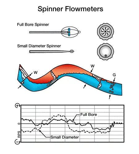
To the right of the schematics are drawings of a casing centralized within the borehole. Inside the casing is a dashed circular area representing the logging tool’s radius of investigation. Notice that the small-diameter spinner is eccentralized and investigates the lower portion of the casing, while the full bore spinner is centralized, and investigates a larger area of the flow.
An undulating horizontal segment of a conventional cemented and perforated completion is shown below the tool schematics. Entries of gas and water occur along its length. If the spinner were responsive to the volumetric flow, it would detect the entries, and the flow volume would increase in steps to the left of each entry point. The log section at the bottom of Figure 1 shows how a spinner would actually respond. The small eccentralized spinner, with its high degree of log curve fluctuation, is easiest to understand in this regard.
Flow regime makes a significant impact on spinner performance. For example, spinners may not be effective in stratified flow. A spinner measuring stratified flow would tend to exhibit a response resembling downflow as the light phase moves up the high side of the pipe when the heavy (water) phase falls out and flows down the lower side of the pipe.
In Figure 1, for example, we see, the spinner detects zero flow prior to gas entry. From the point where the gas entered, the gas will migrate to the top of the borehole and move to the high side of the pipe (toward the left in this example). However, water will also be carried to the left on the high side of the pipe, after which the water will tend to fall back to the low side, since there is no net water production. At some distance beyond the point of water entry, the water fallback will stop, and water will move to the left. This would certainly occur as the crest is approached. The downflow velocity would be high, but would slow down in the trough. In the uphill section, there may yet be some fallback at the low side, depending on the flow rates and angle of the hole. Clearly, the eccentralized small spinner would not be very useful in this environment; indeed, the full-bore spinner is not much better.
Stationary Flow Measurements
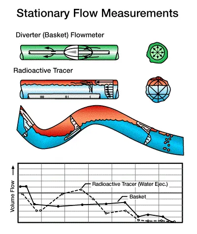
Stationary velocity flow measurements include both the diverter flowmeters (basket or packer types) and the tracer ejector. These tools and their responses to flow in the horizontal environment are shown in Figure 2 – Stationary flow measurements in horizontal wells.
Diverter-Type Flowmeters
The diverter type of flowmeter has been used effectively in horizontal wells. In an undulating section of a horizontal well, the flowmeter diverter basket can detect fluid entry through the well’s conventional completion and will provide a good quantitative indication of bulk flow rate.
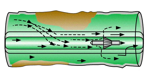
However, if the diverter uses a metal petal basket, its performance will likely be degraded by leakage of the gas phase between the petals and leakage at the point where the petals contact the wall. Diverters also experience a pressure drop associated with flow through the tool. This pressure drop can change the flowing production profile, especially in horizontal wells where pressure drawdowns from formation pressure are not large. Furthermore, diverters may be plagued by debris, which may clog the spinner. This problem is especially prevalent in open-hole completions. Diverters are ineffective in slotted liner completions, since the diverter can force the fluids to simply flow back through the slots and out to the formation–liner annulus, to bypass the basket or packer, as shown in Figure 3 – Problem with basket flowmeters in slotted liner completions.
Radioactive tracers
Radioactive tracer techniques use hydrocarbon and water soluble tracers. Some models of tracer equipment include dual tracer ejectors, in which tracers for one phase or the other may be ejected from the tool. The radioactive tracer is ejected and mixes with its compatible phase. One or more gamma ray detectors are then used to detect the tracer and determine the velocity of its associated phase. This tool has been effective in certain applications, and is the basis for the Phase Velocity Log used on Schlumberger’s Flagship TM tool string, discussed later. Problems with mixing of the tracer and its compatible phase sometimes occur at the phase interface. Increasing the separation distances between the ejector and the detector, or the use of multiple detectors may mitigate these problems. Note that to make sense of this phase velocity data, accurate holdups of each phase must be known.
Fluid Identification Sensors
Fluid identification tools determine which phases are present in the well. Many estimate fluid bulk density, from which they determine the fractions of each of two phases present.
Pressure Differential Devices
The gradiomanometer uses differential pressure transducers to define fluid density. Downhole fluid density can be used for holdup calculations However, gradiomanometers become less effective as well deviations exceed 70. Increasing deviation affects the flow regime, phase segregation and velocity distribution. These can be severely affected by high turbulence – a phenomenon known as the ‘jet effect’. At higher flow rates, friction effects must also be corrected calculating for holdup. In addition, the hydrostatic head created by fluids disappears when two measure points are made at or near the same depth, as seen in horizontal wells.
Nuclear Fluid Density Devices
Nuclear fluid density devices (Figure 4 – Fluid identification devices in horizontal wells) have been used effectively in horizontal wells.
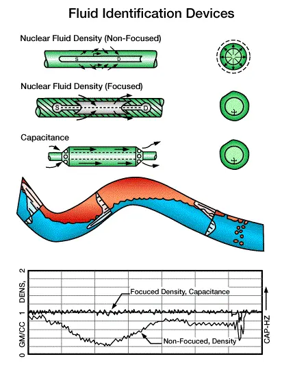
There are both focused and non-focused tool designs. The non-focused tool has a radius of investigation that fills the entire cross-section of the borehole. Theoretically, the source-to-detector spacing (denoted in Figure 4 as S and D respectively) could be adjusted to optimize the region of investigation for maximum effectiveness. This type of tool is commonly used for gravel pack evaluation. When used to obtain holdup values, uncertainties may be introduced by density anomalies outside of the casing (cement channels or gravel pack voids). These tools are not calibrated for holdup measurements.
Focused nuclear fluid density tools have a radius of investigation that is essentially the radius of the tool housing. The fluid must be in contact with the tool in order for it to be measured. In horizontal wellbores, it is common for such tools to indicate nearly 100% water.
Temperature and Noise Logs
Temperature and noise logs both employ a large region of investigation, extending even beyond the casing. Each of these tools can be useful in a conventional or a slotted liner completion. However, both of these tools are qualitative in their interpretation. Temperature and Noise logs are shown in Figure 5 – Temperature and noise logs in horizontal wells.
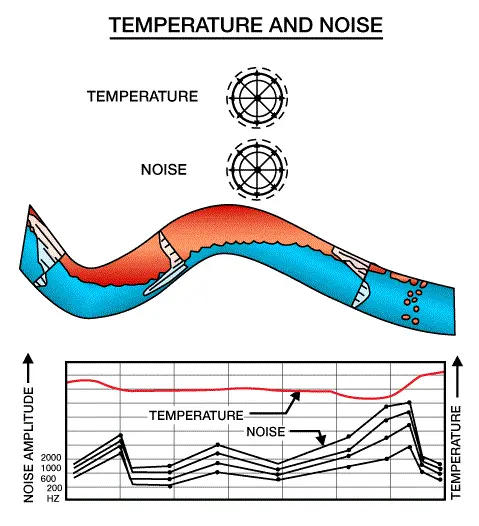
Temperature Log
The normal temperature gradient of a well tends to change as fluids enter or leave the wellbore. The temperature log can show gas entries by a cooling anomaly, and liquid entries may be detected by their effect upon mixing with the flow. Temperature logs are effective in vertical wells because of the presence of the geothermal gradient. However, in the horizontal environment, such gradients are non-existent and pressure drawdowns are low. As a result, anomalies are likely to be very small or non-existent. Indeed, it is common to record temperature logs on a scale of only one or two degrees across the logging track.
Noise Log
Noise logs can probably detect the bubbling gas entry without any trouble. However, low pressure drawdowns on the formation may cause liquid entries to be slow and spread over long intervals. Such entries would produce little noise and would probably be quite difficult to detect.
Oxygen Activation/Water Flow
The oxygen activation effect was first observed as an increase in background count rates from pulsed neutron capture logs. When the tool’s neutron generator produces a neutron burst, any nearby oxygen will be activated to produce an unstable nitrogen isotope with a half-life of slightly more than seven seconds. As the activated nitrogen returns to native oxygen, gamma rays will be given off. If water flows near the tool at a velocity greater than the speed of the logging tool, then the activated oxygen within the water will be carried past the near and far detectors, causing the measured gamma ray count rate at the near and far detectors to increase over the background reading.
The oxygen activation principle has been refined to make quantitative measurements of water velocity. In this application, the tool, which incorporates a pulsed neutron generator and an array of detectors, makes a stationary measurement. A schematic of a stationary velocity test, showing the location of the tool’s near (N) and far (F) detectors, is shown in Figure 6 – Oxygen activation water flow measured in horizontal completions.
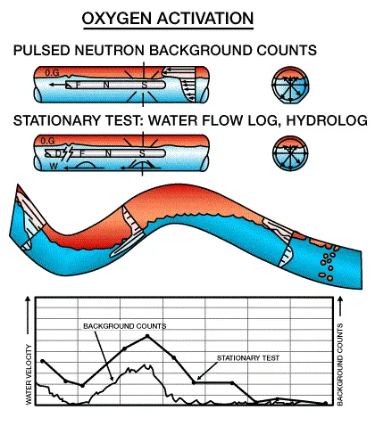
Essentially, the pulsed neutron generator is used to activate the oxygen nuclei within the flowing water stream. The activated oxygen nuclei give off gamma rays at a known rate as the oxygen returns to its original state. These gamma rays are detected and counted by the tool. The gamma ray count rate can be calibrated against the known oxygen decay rate to ascertain the direction and velocity of the water flow. The count rate will be identical to the known half-life rate if the water is stationary. Count rates will increase if the water moves toward the tool, and will decrease if the water moves away from the tool.
Three detectors are typically spaced at varying distances from the neutron source to measure the fluid velocity before the signal dies away with the fading of the short half-life of the activated oxygen. This technique is very similar in principle to that of the radioactive tracer, except that only the water phase can be measured.
Useful Ancillary Information
An indication of wellbore trajectory is needed to make a reliable interpretation of production log data in horizontal wells, where fluids tend to segregate by phase density because undulations, crests, and troughs influence the behavior of the flows. Ideally, the production logging tool string should have an inclinometer to measure the borehole angle relative to true horizontal. Crests and troughs can then be readily distinguished. If an inclinometer is not available, then directional data from earlier logging runs or drilling records must be consulted.
The gravel pack log is another important ancillary measurement that may be needed for slotted liner completions. The log may help to determine whether the formation has collapsed onto the liner. In areas where the formation has collapsed, annular flows will be diverted into the liner thus appearing as a fluid entry, while providing no true indication of the zone that the fluid was produced from. However, along the interval in which the formation collapsed, the completion essentially resembles a “conventional” completion, so the flow in this interval is more easily measured and understood.
A gamma ray tool and casing collar locator should be included in the toolstring to correlate the production log to open-hole data or earlier production log runs.
